Catalog excerpts

Bulletin 71.1:133 January 2007 133 Series Self-Operated Regulators Features • Wide Pressure Range Capability with Single Regulator—Type 133H may also use Type 133L springs, allowing pressure settings to be varied between 2-inches w.c. and 10 psig (5 mbar and 0,69 bar) by changing springs. • Types 133L, 133H and 133HP Suitable for Monitoring Applications—O-ring stem seal on Types 133L, 133H and 133HP isolates body pressure from controlled pressure. • Excellent Shock Characteristics and Fast Speed of Response—Due to two-way stabilizer vent valve, which vents the spring case more rapidly than conventional vents, lag in diaphragm and valve disk movement is minimized. W1327/IL types 133H, 133l and 133z regulators • Bubble-Tight Shutoff—Single-port construction, large diaphragm area, and light-rate springs along with disk material and seat design provide low lock-up pressures. • Spring and Diaphragm Effects Minimized boosting system provides excellent performance over a wide range of flow conditions. • No Seat-to-Seat Adjustment Required—Balanced single-port design eliminates necessity for seat-to seat adjustments to achieve bubble tight shutoff. • Easy Access to Trim Parts—Valve seat, disk, and cage easily removed with body remaining in line and without disassembly of actuator portion; orifice is not threaded in. • Reusable Pressure Seals—O-rings used for pressure seals, unlike gaskets, are not ordinarily damaged by disassembling the regulator. • Resistance to Piping Stresses—Steel constructions are available to help resist pipe stresses. W6803/IL type 133hp regulator D100118X012 Figure 1. 133 Series Self-Operated Regulators www.emersonprocess.com/regulators
Open the catalog to page 1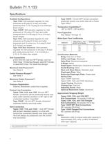
Available Configurations Type 133H: Self-operated regulator for inlet pressures to 60 psig (4,14 bar) and outlet pressures from 1.5 to 10 psig (0,10 to 0,69 bar), three ranges Type 133HP: Self-operated regulator for inlet pressures to 150 psig (10,3 bar) and outlet pressures from 2 to 60 psig (0,14 to 4,14 bar), seven ranges Type 133L: Self-operated regulator for inlet pressures to 60 psig (4,14 bar) and outlet pressures from 2-inches w.c. to 2 psig (5 mbar Type 133Z Zero Governor: Self-operated regulator for inlet pressures to 20 psig (1,38 bar) and outlet pressures from -1 to 4-inches...
Open the catalog to page 2
Bulletin 71.1:133 W1213-1/IL W1212-1/IL TYPE 133Z ZERO GOVERNOR TYPE 133L LOW-PRESSURE REGULATOR Restriction collar Identification groove 1 orifice Set screw Cage W2215-1* Valve disk e-ring TRIM PARTS WITH RESTRICTION COLLAR (40% CAPACITY COLLAR IS SHOWN) W1211-1 TYPE 133H WITHOUT RESTRICTION COLLAR 1 IDENTIFICATION GROOVES: 25% CAPACITY COLLAR—NO GROOVES 40% CAPACITY COLLAR—ONE GROOVE 60% CAPACITY COLLAR—TWO GROOVES Figure 2. Types 133Z, 133L and 133H Regulators
Open the catalog to page 3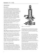
Bulletin 71.1:133 Introduction Description The 133 Series self-operated gas regulators, shown on the cover are primarily designed for industrial and commercial applications supplying gas to furnaces, burners and other appliances. The 133 Series balancing system enables the regulator to provide accurate control of gas pressure for maximum combustion efficiency despite varying inlet pressure conditions. The single port construction provides bubble tight shutoff. An external downstream control line is required for the operation of the regulator. Refer to Table 1 for outlet pressure ranges of...
Open the catalog to page 4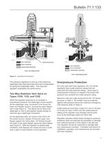
Bulletin 71.1:133 Balancing Diaphragm B0098-3/IL Inlet pressure Registration disk Boost pressure Downstream pressure Type 133L regulator Figure 4. Operational Schematics This pressure registered on the top of the balancing diaphragm aids downward disk travel and compensates for spring and diaphragm effect. This improves regulator rangeability and performance. Two-Way Stabilizer Vent Valve on Types 133H, 133L and 133Z When the regulator responds to an increase in downstream pressure, the diaphragm moves upward. As the diaphragm rises, movement of air forces the lower vent flapper upward,...
Open the catalog to page 5
Table 1. 133 Series Outlet Pressure Ranges, Control Springs Table 2. Maximum Inlet and Outlet Pressures Capacity Data Flow capacities for various inlet pressures and outlet pressure settings are shown in Tables 3 to 10. Capacities for Tables 3 to 10 are in thousands of cubic feet per hour of 0.6 specific gravity gas at 60°F and 14.7 psia. To convert to equivalent capacities of other gases, multiply the values shown by the appropriate For optimum performance, select the lowest spring range that includes the desired outlet pressure setting. For restricted-capacity constructions, determine...
Open the catalog to page 6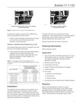
TWO-WAY STABILIZER VENT VALVE IN "UP" POSITION Figure 5. Types 133H, 133L and 133Z Stabilizer Vent To determine capacity using the flow coefficient Cg, use the appropriate procedure below. 1. If flow is critical (absolute outlet pressure is equal to or less than one-half the absolute inlet Capacity = (Absolute Inlet Pressure) (Cg) (1.29) The capacity determined will be in standard cubic feet per hour of 0.6 specific gravity gas. 2. If flow is less than critical (absolute outlet pressure is greater than one-half the absolute inlet pressure), use the Fisher sizing slide rule or the sizing...
Open the catalog to page 7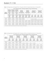
Table 4. Full-Capacity Type 133L Regulated Flow in Thousands of SCFH of 0.6 Specific Gravity Gas at 14.7 Psia and 60"F Table 5. Full-Capacity Type 133H Regulated Flow in Thousands of SCFH of (0.6 Specific Gravity Gas at 14.7 Psia and 60"F)
Open the catalog to page 8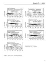
. SPRING COMPRESSION - 1D892527022 EXTENSION - 1K663427012 SETPOINT: INLET PRESSURE 1 PSIG (0,07 bar] OUTLET PRESSURE 1-INCH W.C. (2 mbar] SETPOINT: INLET PRESSURE 40 PSIG (2,76 bar) OUTLET PRESSURE 1 PSIG (0,07 bar) 20 PSIG 30 PSIG 40 PSIG 50 PSIG 60 PSIG SETPOINT: INLET PRESSURE 2 PSIG (0,14 bar) 1 PSIG 2 PSIG 3 PSIG 5 PSIG SETPOINT: INLET PRESSURE 40 PSIG (2,76 bar) OUTLET PRESSURE 1 PSIG (0,07 bar) SETPOINT: INLET PRESSURE 40 PSIG (2,76 bar) OUTLET PRESSURE 7-INCH W.C. (17 mbar) 10 PSIG 20 PSIG 30 PSIG 40 PSIG 50 PSIG 60 PSIG SETPOINT: INLET PRESSURE 40 PSIG (2,76 bar) OUTLET PRESSURE...
Open the catalog to page 9All FISHER REGULATORS catalogs and technical brochures
-
™ Control Valves and Instruments
16 Pages
-
Run with higher performing,
16 Pages
-
R Series
2 Pages
-
LP-Gas Technologies
118 Pages
-
Industrial Regulators
2 Pages
-
Type 92B Pressure Reducing Valve
16 Pages
-
Type 630R Relief Valve
8 Pages
-
Fisher™ 585C Piston Actuators
16 Pages
-
Type 630 Regulator
16 Pages
-
Fisher™ YD and YS Control Valves
24 Pages
-
easy-e Cryogenic Valves
12 Pages
-
Large ET and ED Valves
20 Pages
-
1305 Series Regulators
4 Pages
-
H200 Series Relief Valves
4 Pages
-
Air Application Map
1 Pages
-
DeltaV Controller Firewall
11 Pages
-
CSI 6500 Overview
12 Pages
-
The Criticality of Cooling
5 Pages
-
Ovation Security Center
4 Pages
-
DeltaV Smart Switches
28 Pages
-
Smartprocess™ Heater
5 Pages
-
FPSO Industry Solution
2 Pages
-
LP-31
96 Pages
-
CS 200 series
2 Pages
-
Regulators Mini Catalog
24 Pages
-
1301F, 1301G
12 Pages
-
MR95 and MR98
2 Pages
-
Fisher® D and DA Valves
12 Pages
-
Fisher® EZ easy-e Control Valve
40 Pages
-
Fisher® YD and YS Control Valves
24 Pages
-
Fisher® HPNS Control Valve
36 Pages
-
Fisher® HP Series Control Valves
28 Pages
-
Fisher® CAV4 Control Valve
28 Pages
-
Fisher® 377 Trip Valve
20 Pages
-
EZR Pressure Reducing Regulator
36 Pages
-
630 Regulator
16 Pages
-
627F Pressure Reducing Regulator
12 Pages
-
ACE97 Pad-Depad Valve
16 Pages
-
310A Pressure Reducing Regulator
16 Pages
-
S200 series
32 Pages
-
R622 series
8 Pages
-
Type HSR Pressure Regulators
20 Pages
-
cs200 series
40 Pages
-
CS400 Series
60 Pages
-
167D Series Switching Valves
8 Pages
Archived catalogs
-
Vapor Pressures of LP-Gas
1 Pages
-
Pipe and Tubing Sizing
1 Pages
-
Average Properties of LP-Gas
1 Pages
-
Pressure Equivalents
1 Pages


