- Catalogs
- Fischer Connectors
- Fischer Core Series Plastic
- Company
- Products
- Catalogs
- News & Trends
- Exhibitions
Fischer Core Series Plastic
1 /20Pages

Fischer Core Series Plastic
1 /20Pages
Catalog excerpts
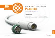
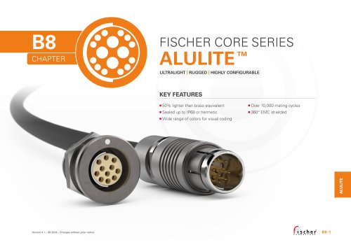
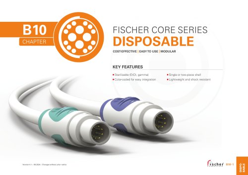
FISCHER CORE SERIES EASY TO USE | DURABLE | LIGHTWEIGHT KEY FEATURES Over 5,000 mating cycles Resistant to large temperarure variations Color coding for easy operation Version 4.1 − 08.2024 − Changes without prior notice
Open the catalog to page 1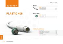
FISCHER CORE SERIES PLASTIC This catalog covers our standard connector solutions. For specific requests, including hybrid or custom connectors, please contact your local sales representative. Technical Specifications
Open the catalog to page 2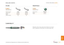
Body styles selection FISCHER CORE SERIES PLASTIC CABLE MOUNTED PANEL MOUNTED BODY STYLES Locking system Sealing Design Integral shielding BODY STYLE Sealing Design Mateable with all high performance Fischer Connectors’ panel receptacles of the Fischer Core Series Brass 105. All dimensions and images shown are in millimeters and are for reference only.
Open the catalog to page 3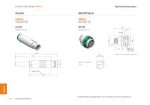
Technical dimensions FISCHER CORE SERIES PLASTIC CABLE MOUNTED PANEL MOUNTED BODY STYLES BODY STYLE * See contact configurations page B 9-6. PANEL CUT-OUT Figure 1 Technical Specifications All dimensions and images shown are in millimeters and are for reference only
Open the catalog to page 4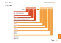
Part numbering FISCHER CORE SERIES PLASTIC PLASTIC 405 Standard options Body style S= Plug, with integral shielding SI = Plug, without integral shielding DBP = Receptacle, rear panel mounted Series A = Plugs have male contacts. Receptacles have female contacts. Z = Plugs have female contacts. Receptacles have male contacts. Contact configuration See page B 9-6 Body color B = Beige C = Anthracite Insulator material 3 = PEEK Contact type J = Solder K = Crimp L = PCB Color coding 2 = Anthracite 3 = Green 4 = Blue 5 = Yellow 8 = Beige Bend relief material R = None S = Silicone (6.5 dia.) T = TPE...
Open the catalog to page 5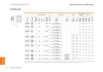
Electrical & contact configurations FISCHER CORE SERIES PLASTIC Technical Specifications Crimp contacts Solder contacts Insulating material Test voltage [kV] in mated position Wire size Contact types Current per contact at 40°C temperature rise measured on the basic curve according to IEC 60512-5-2-5b. For the max. operating current a reduction factor must be used and limitations due to the size of the wires and the permissible upper temperature limit of the
Open the catalog to page 6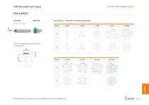
PCB hole pattern pin layout FISCHER CORE SERIES PLASTIC View from F - Number of contacts (reference) Minimum clearance for ground lug of receptacle. All dimensions and images shown are i
Open the catalog to page 7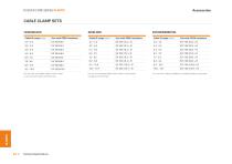
FISCHER CORE SERIES PLASTIC CABLE CLAMP SETS UNSHIELDED Use with PEEK Insulators Use with PEEK insulators Use with PEEK insulators For use with unshielded cable or when shield is not carried through connector body. Technical Specifications For use with shielded cable when shield is to be carried through connector body. For use when sealing shielded or unshielded cable to plug body.
Open the catalog to page 8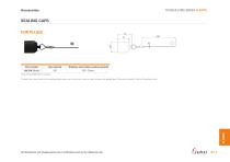
FISCHER CORE SERIES PLASTIC SEALING CAPS FOR PLUGS Part number Stainless steel cable covering material Crimp ferrule (300.637) is included. To attach the crimp ferrule to the stainless steel cable, use a crimp tool, a vice or a pair of pliers with parallel jaws. There are no specific Fischer Connectors tools. All dimensions and images shown are in millimeters and are for reference only.
Open the catalog to page 9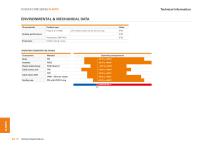
Technical information FISCHER CORE SERIES PLASTIC ENVIRONMENTAL & MECHANICAL DATA Characteristic Product type Plug (S or SI 405) Value with sealed cable clamp set and cap Sealing performance OPERATING TEMPERATURE RANGE Component Plastic Cable Clamp Cable clamp seal Cable strain relief Sealing cap
Open the catalog to page 10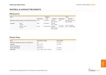
Technical information FISCHER CORE SERIES PLASTIC MATERIAL & SURFACE TREATMENTS Metal parts Parts Material Designation Metal parts (except contacts), inner body shell of S plug Brass Male (solder) Female, male (crimp) 1 µm Gold over Nickel Plastic Parts International symbol Body shell, sealing cap, back nut, mounting nut PEEK - PTFE Plastic cable clamps Bend relief TPE-S - VMQ - Silicone Rubber All dimensions and images shown are in millimeters and are for reference only.
Open the catalog to page 11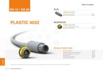
FISCHER CORE SERIES PLASTIC This catalog covers our standard connector solutions. For specific requests, including hybrid or custom connectors, please contact your local sales representative. Technical Specifications
Open the catalog to page 12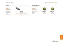
Body style selection CABLE MOUNTED PANEL MOUNTED BODY STYLE Locking system Sealing Design Integral shielding SI 4032 Push-pull P50 / IP68 with cap or mated with DBPO Standard No BODY STYLES Sealing Design FISCHER CORE SERIES PLASTIC
Open the catalog to page 13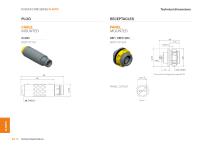
Technical dimensions FISCHER CORE SERIES PLASTIC CABLE MOUNTED PANEL MOUNTED BODY STYLE BODY STYLES * See contact configurations page B 9-16. PANEL CUT-OUT Technical Specifications
Open the catalog to page 14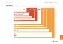
Part numbering FISCHER CORE SERIES PLASTIC PLASTIC 4032 Housing design Standard options Body style Plug = SI Receptacle, rear panel mounted = DBP Receptacle, rear panel mounted, sealed when mated (IP68) = DBPO Series Plugs have male contacts. Receptacles have female contacts = A Plugs have female contacts. Receptacles have male contacts. = Z Contact configuration Body material Insulator material PEEK = 3 Contact type Solder = J Crimp = K PCB = L Color coding White = 1 Black = 2 Green = 3 Blue = 4 Yellow = 5 Red = 6 Grey = 7 Bend relief material
Open the catalog to page 15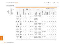
Electrical & contact configurations FISCHER CORE SERIES PLASTIC Technical Specifications Test voltage [kV] in mated position Crimp contacts Insulating material Wire size Contact types Current per contact at 40°C temperature rise measured on the basic curve according to IEC 60512-5-2-5b. For the max. operating current a reduction factor must be used and limitations due to the size of the wires and the permissible upper temperature limit of the materials employed
Open the catalog to page 16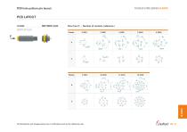
PCB hole pattern pin layout FISCHER CORE SERIES PLASTIC View from F - Number of contacts ( reference ) BODY STYLES All dimensions and images shown are in millime
Open the catalog to page 17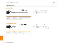
FISCHER CORE SERIES PLASTIC SEALING CAPS FOR PLUGS ~150 Part number Stainless steel cable covering material Crimp ferrule (300.922) and heat shrink tube (300.930) are included. Part number Stainless steel cable covering material Crimp ferrule (300.922), crimp lug (300.299) and heat shrink tube (300.930) are included. To attach the crimp ferrule or the crimp lug to the stainless steel cable, use a crimp tool, a vice or a pair of pliers with parallel jaws. See page B6-22 for recommended crimping tool for ferrule. Technical Spec
Open the catalog to page 18All Fischer Connectors catalogs and technical brochures
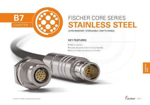
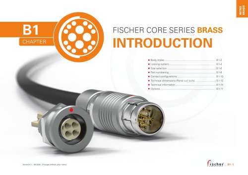 Fischer Core Series Brass
178 Pages
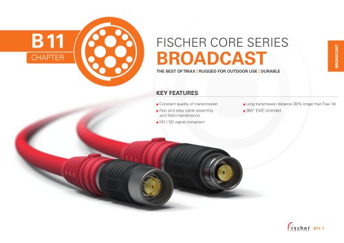 Fischer Core Series Broadcast
29 Pages
 Fischer Core Series Alulite™
32 Pages
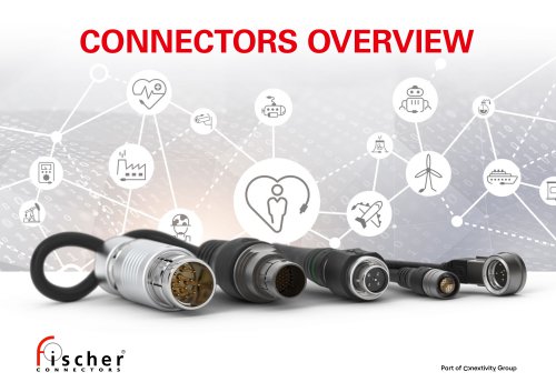 Connectors Overview
2 Pages
 Cable Assembly Solutions
4 Pages
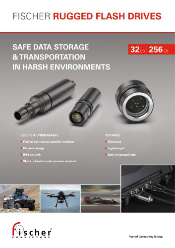 Fischer Rugged Flash Drives
4 Pages
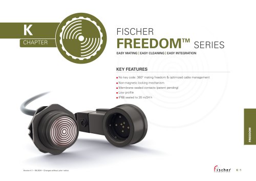 Fischer Freedom™ Series
18 Pages
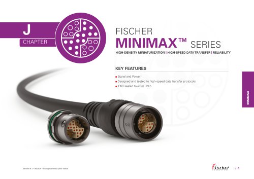 Fischer MiniMax™ Series
27 Pages
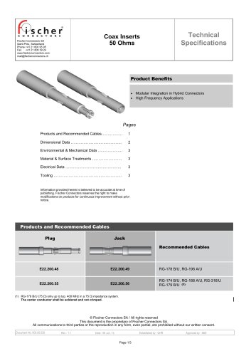 Coax Inserts 50 Ohms
3 Pages
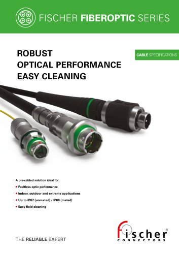
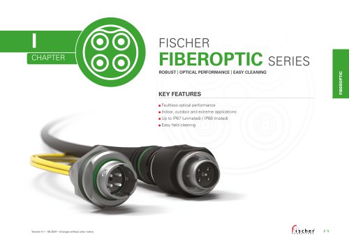 Fischer FiberOptic Series
32 Pages
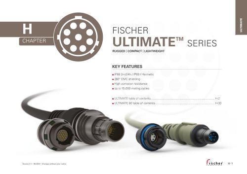 Fischer UltiMate™ Series
45 Pages
 Technical Specifications Volume 2
148 Pages
 Technical Specifications Volume 1
293 Pages
- Fischer data connector
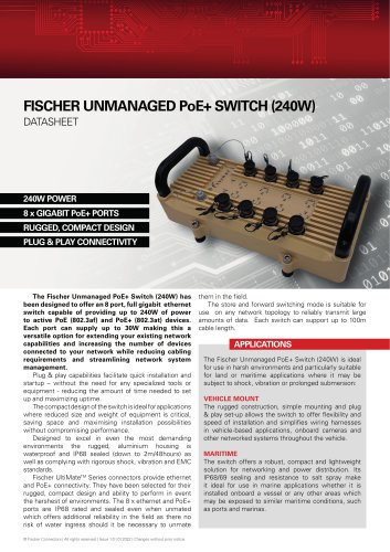
- Ethernet switch
- Fischer electrical power supply connector
- Fischer metal connector
- Fischer round connector
- Polymer connector
- Screw-in connector
- Fischer industrial connector
- Gigabit ethernet switch
- Fischer circular connector
- IP67 connector
- Unmanaged switch
- Fischer cable connector
- Current connector
- PoE network switch
- Cable assembly
- Rugged network switch
- Fischer brass connector
- Fischer voltage connector