
Catalog excerpts
The first successful application of airsprings for vibration isolation occurred during the late nineteen thirties. Airsprings were developed by Firestone to fill a need for a more efficient suspension system for highway trucks, trailers, and buses. Airide™ springs, as they were named, provided the means for a suspension that reduced the amount of road shock and vibration transmitted into the vehicle. Billions of miles of actual use have proven the dependability and effectiveness of the air suspension concept using Airide springs by Firestone. Airmount isolators and Airstroke actuators are a...
Open the catalog to page 2
™ AIRSTROKE ACTUATORS Style Number Minimum Height (inches) Maximum Stroke (inches) 80 PSI Force* at Stroke of 1 Inch 3 Inches Maximum Stroke (pounds) (pounds) (pounds) Advantages of: SHAPED SLEEVE 1M1A-0 1M1A-1 2M1A 2M2A 1.5 1.5 2.5 1.2 1.4 2.0 3.4 1.0 450 490 470 10.8 410 400 375 360 10.8 SINGLE CONVOLUTION 16 16ST 131 110 116 116-1 115 19 19-.75 113 113-1 153-2 119** 121** 126** 138-1.5 148-1 1.9 1.8 2.0 2.0 2.0 2.0 2.0 2.0 2.0 2.0 2.0 2.5 2.0 2.0 2.0 2.0 2.5 1.4 1.5 2.1 3.1 3.1 4.2 3.1 3.5 3.9 3.8 4.6 4.8 4.2 3.6 4.4 5.3 4.8 960 930 1,350 2,090 2,690 2,980 3,550 6,720 7,040 9,900 10,860...
Open the catalog to page 4
Airstroke Actuator Selection Procedure ™ Refer to the selection guide on page 4 for Airstroke actuator force and stroke capabilities. This information is intended to give a general guide to part capabilities. Before selecting the correct Airstroke actuator you need to know certain attributes of your application. Once this data is known, the selection is relatively easy. For more detailed information please obtain a copy of Firestone’s Engineering Manual and Design Guide. generally decreases as height increases. If you have less than 100 psi available, divide the force by 100 and multiply by...
Open the catalog to page 5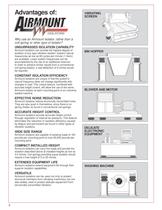
Advantages of: VIBRATING SCREEN Why use an Airmount isolator, rather than a coil spring or other type of isolator? UNSURPASSED ISOLATION CAPABILITY Airmount isolators can provide the highest degree of isolation of any type vibration isolator. System natural frequencies as low as 60 cycles per minute (1 Hertz) are available. Lower system frequencies can be accomplished by the use of an additional reservoir. In order to achieve similar results from a conventional coil spring isolator, a real deflection of 9 inches would be required. BIN HOPPER CONSTANT ISOLATION EFFICIENCY Airmount isolators...
Open the catalog to page 6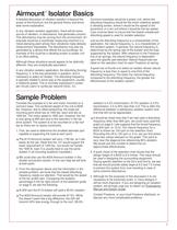
Airmount Isolator Basics ™ A detailed discussion of vibration isolation is beyond the scope of this brochure, but the general theory and terms bear some explanation. In any vibration isolation application, there will be some source of vibration, or disturbance, that generates concern. This disturbance may be coming from the environment. An example would be a coordinate measuring machine in a metal stamping plant whose floor vibrations make delicate measurement impossible. The disturbance may also be generated by a device that affects the surroundings. An example of this could be a vibrating...
Open the catalog to page 7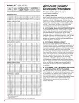
™ Airmount Isolator Selection Procedure AIRMOUNT ISOLATORS Style Number Design Height Load (at Natural Design Height) Frequency at 100 PSIG (@ 80 PSIG) (pounds) fn(cpm) ™ % of Isolation at Forced Frequency 400 CPM 800 CPM % % Refer to the selection guide on this page for Airmount isolator capabilities. SHAPED SLEEVE 1M1A-0 1M1A-1 2M1A 2M2A 2.5 570 220 3.0 593 162 90.0 DO NOT USE 2M1A AS AN AIRMOUNT ISOLATOR 2.0 198 232 1. LOAD CAPACITY 91.8 95.5 Select one or two Airmount isolators that can support the load at each mounting point. It is normally best to design for pressures in the 60 to 80...
Open the catalog to page 8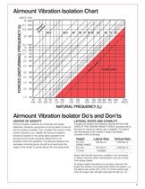
Airmount Vibration Isolation Chart 41.7 2500 33.2 2000 P Is erc ol e at nt io n 99.9 99.5 99 98 97 96 95 90 80 70 60 25 1500 16.7 15 13.3 11.7 10 1000 900 800 700 600 8.3 500 Re so na nc e FORCED (DISTURBING) FREQUENCY (ff) HERTZ CPM 50 3000 6.7 400 5.0 300 Amplification 4.2 250 3.3 200 2.5 150 1.7 100 30 0.50 40 50 60 0.67 0.83 1.0 80 100 1.33 1.67 150 2.50 200 3.33 300 5.00 400 500 600 800 1000 6.67 8.33 10.0 13.3 16.7 CPM HERTZ NATURAL FREQUENCY (fn) Airmount Vibration Isolator Do’s and Don’ts CENTER OF GRAVITY LATERAL RATES AND STABILITY Airmount isolator systems are inherently soft...
Open the catalog to page 9
PLUMBING SYSTEMS There are three basic ways of controlling an air suspended isolation system: 1. Tank Valve System–With a TANK VALVE in each isolator, each air spring can be inflated individually. The pressure in each must be checked periodically, because air will permeate through the bellows. For an idea of the permeation rate, a #116 will lose approximately 30 psig over a period of one year (from 100 psig to 70 psig). 2. Three Point Regulated System–The Airmount isolators can be connected directly to the factory compressed air system using pressure regulating valves. This eliminates the...
Open the catalog to page 10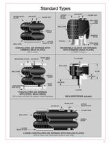
Standard Types AIR INLET UPPER BEAD PLATE AIR INLET UPPER BEAD PLATE BLIND NUT BLIND NUT BELLOWS END CLOSURE BELLOWS GIRDLE HOOP BUMPER STUD PISTON LOWER BEAD PLATE BELLOWS THREADED HOLE CONVOLUTED AIR SPRINGS WITH CRIMPED BEAD PLATES REVERSIBLE SLEEVE AIR SPRINGS WITH CRIMPED BEAD PLATES (#22 is shown) (1T15M-6 is shown) MOUNTING PLATE AIR INLET BEAD RING BOLT 5/16-18 UNC BELLOWS 3.0 IN. BELLOWS GIRDLE HOOP BEAD RING LOCKWASHERS AND NUTS 1.50 INCH 1.00 INCH 1/8-NPTF CONVOLUTED AIR SPRINGS WITH STEEL BEAD RINGS (#22 is shown, with bead rings instead of crimped bead plate) 1M1A AIRSTROKE...
Open the catalog to page 11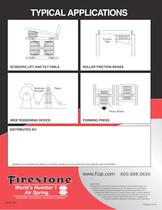
TYPICAL APPLICATIONS Friction Pad SCISSORS LIFT AND TILT TABLE Airstroke Actuator ROLLER FRICTION BRAKE Paper Press Platen WEB TENSIONING DEVICE FORMING PRESS DISTRIBUTED BY: Request our Engineering Manual & Design Guide for more extensive and specific part information. www.fsip.com 800.888.0650 PLEASE NOTE: The information contained in this publication is intended to provide a general guide to the characteristics and applications of these products. The material, herein, was developed through engineering design and development, testing and actual applications and is believed to be reliable...
Open the catalog to page 12All Firestone Industrial catalogs and technical brochures
-
Date Codes Sheet
2 Pages
-
Corporate Brochure
2 Pages
-
Air Spring Maintenance
4 Pages
-
Marshmellow Brochure MM
4 Pages
-
DR Series Flyer DRS_A4
2 Pages
-
Airstroke Airmount brochure
12 Pages
-
Airide Design Guide Design Guide
84 Pages
-
Airail Springs Design Guide Rail
52 Pages
-
Aftermarket LoadShare
28 Pages
-
Aftermarket BUS_014
50 Pages
-
Aftermarket Catalog Mexico MXCAT
251 Pages
-
Marshmellow Brochure
60 Pages
-
Airstroke/Airmount Brochure
12 Pages


