
- Catalogs
- FIP - Formatura Iniezione Polimeri
- TKD DN 10÷50


- Company
- Products
- Catalogs
- News & Trends
- Exhibitions
TKD DN 10÷50
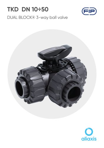
TKD DN 10÷50
- Patented SEAT STOP® ball carrier system for precise ball seat adjustments.
- Easy radial dismounting for quick O-ring and ball seat replacement without tools.
- PN16 True Union valve body made from rigid PVC-U, meeting ISO 9393 test standards.
- Capability to dismount downstream pipes while the valve is closed.
- High surface finish stem with double O-Ring and visual ball position indicator.
- Integrated bracket for valve anchoring and compatibility with pneumatic/electric actuators.
- Construction: 3-way True Union ball valve with locked carrier and union nuts.
- Size Range: DN 10 ÷ 50.
- Nominal Pressure: PN 16 with water at 20°C.
- Temperature Range: 0°C ÷ 60°C.
- Coupling Standards: Includes EN ISO 1452 and ASTM D 2467.
- Valve Material: PVC-U; Seal Material: EPDM, FKM, with options for FEP+FKM, FFKM.
- Available in manual, electric actuator, and pneumatic actuator options.
- Ergonomic handle with removable tool for ball seat carrier adjustment.
- DUAL BLOCK® patented lock system for secure union nut tightening.
- Pressure variation according to temperature for chemically resistant fluids.
- Includes pressure drop graph and work positions for T-port and L-port ball valves.
- Kv100 flow coefficient table provided for various DN sizes.
- Detailed dimensions for various valve configurations and sizes.
- Accessories include handle block kits, stroke limiters, stem extensions, and actuator modules.
- Step-by-step instructions for disassembly and assembly of valve components.
- Exploded view and component list provided for reference.
- Ensure pipes are aligned to prevent mechanical stress on threaded joints.
- Verify the DUAL BLOCK® union nut locking device is fitted to the valve body.
- To release union nuts, press the release lever axially and unscrew counter-clockwise.
- Unscrew the three union nuts and place them on the pipe segments.
- Solvent weld or screw end connectors onto pipe ends.
- Position the valve body between end connectors and manually tighten union nuts clockwise.
- Lock union nuts by pressing the DUAL BLOCK® until hinges lock.
- Support pipework with FIP pipe clips or built-in valve carrier if necessary.
- Handle lock available to prevent ball rotation; can be secured with a padlock.
- Seals adjustable using extractable insert on the handle.
- Micro adjustment possible with FIP valves using the patented "Seat stop system" for seal recovery.
- Avoid sudden closing maneuvers and protect the valve from accidental operations.
Catalog excerpts

TKD DN 10÷50 DUAL BLOCK® 3-way ball valve
Open the catalog to page 1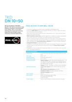
FIP has developed a TKD DUAL BLOCK® ball valve to introduce a high reference standard in thermosplastic valve design. TKD is a True Union diverting and mixing ball valve that meets the most stringent needs required in industrial applications. DUAL BLOCyJ DUAL BLOCK® 3-WAY BALL VALVE • Connection system for solvent weld, threaded and flanged joints • Patented SEAT STOP® ball carrier system that lets you micro-adjust ball seats and minimise axial force effects • Easy radial dismounting allowing quick replacement of O-rings and ball seats without any need for tools • PN16 True Union valve body made...
Open the catalog to page 2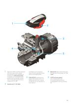
Ergonomic HIPVC handle equipped with removable tool to adjust the ball seat carrier. Possibility of installing the LTKD stroke limiter (available as an accessory) that permits ball and handle rotation only for set opening and closing angles at 90° or 180° (available as an accessory) ergonomically operable during service and padlockable 3 DUAL BLOCK® patented lock system that ensures union nut tightening hold even in severe conditions such as vibrations or heat dilation 4 Ball shutter high surface finish with floating type full passage with T or that compensates axial force guaranteeing optimal...
Open the catalog to page 3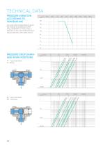
For water and harmless fluids to which the material is classified as CHEMICALLY RESISTANT. In other cases, a reduction of the nominal PN pressure is required (25 years with safety factor). TECHNICAL DATAPRESSURE VARIATION ACCORDING TO TEMPERATUREPRESSURE DROP GRAPH AND WORK POSITIONS A - T-port ball valve: 0°- Mixing B - T-port ball valve: 90° - Diverting
Open the catalog to page 4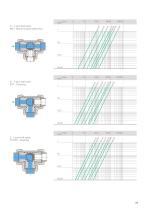
C - T-port ball valve: 180° - Branch closed/direct flow D - T-port ball valve: 270° - Diverting E - L-port ball valve: 0°/270° - Diverting
Open the catalog to page 5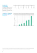
KV100 FLOW COEFFICIENT The K100 flow coefficient is the Q flow rate of litres per minute of water at a temperature of 20°C that will generate Ap= 1 bar pressure drop at a certain valve position. The Kv100 values shown in the table are calculated with the valve completely open. The information in this leaflet is provided in good faith. No liability will be accepted concerning technical data that is not directly covered by recognised international standards. FIP reserves the right to carry out any modification. Products must be installed and maintained by qualified personnel.
Open the catalog to page 6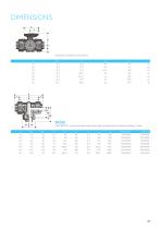
Dimensions shared by all versions
Open the catalog to page 7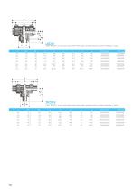
LKDIVDUAL BLOCK® 3-way ball valve with metric plain socket ends for solvent welding, L bore. d TKDDVDUAL BLOCK® 3-way ball valve with metric plain spigot ends for solvent welding, T bore d
Open the catalog to page 8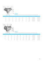
LKDDVDUAL BLOCK® 3-way ball valve with metric plain spigot ends for solvent welding, L bore d DUAL BLOCK® 3-way ball valve with BS plain socket ends for solvent welding, T bore.
Open the catalog to page 9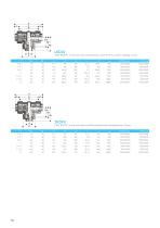
LKDLVDUAL BLOCK® 3-way ball valve with BS plain socket ends for solvent welding, L bore. d DUAL BLOCK® 3-way ball valve with BS parallel socket threaded ends, T bore.
Open the catalog to page 10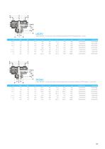
LKDFVDUAL BLOCK® 3-way ball valve with BS parallel socket threaded ends, L bore. R DUAL BLOCK® 3-way ball valve with female ends for solvent welding, ASTM series, T-port ball.
Open the catalog to page 11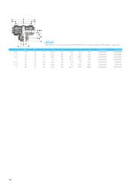
LKDAVDUAL BLOCK® 3-way ball valve with female ends for solvent welding, ASTM series, L-port ball. d
Open the catalog to page 12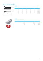
CVDELong spigot PE100 end connectors for joints with electrofusion fittings or for butt welding d
Open the catalog to page 13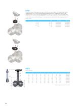
The LTKD stroke limiter specifically permits handle and ball rotation only at set opening and closing angles. The LTKD090 version permits operations for 90° angles while the LTKD180 version for 180° angles. The LTKD stroke limiter is made up of a single removable plate made of technopolymer. Designed for ISO 5211 bore and specifically designed to be directly housed on the valve body mounting flange. It is secured to the valve body by self-tapping screws or plastic rivets. d * Pipe and glue not included in the KIT
Open the catalog to page 14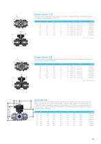
Power Quick/CP The valve can be equipped with pneumatic actuators, using the PP-GR module reproducing the drilling pattern foreseen by ISO 5211
Open the catalog to page 15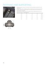
All valves, whether manual or actuated, must be adequately supported in many applications. The TKD valve series is therefore ready to be equipped with threaded supporting brackets (optional) that permits direct anchoring of the valve body without the need of other components. Using standard threaded nuts (not included) made of STAINLESS steel, you can anchor the valve on 4 fastening points.
Open the catalog to page 16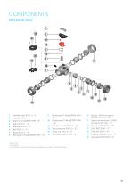
1 Handle insert (PVC-U - 1) 3 Stem O-ring (EPDM-FKM - 2)1 5 Ball seat (PTFE - 4)1 8 Ball seat O-Rings (EPDM-FKM - 4) 9 Radial seal O-Ring (EPDM-FKM -3) 10 Socket seal O-Ring (EPDM-FKM - 3)1 11 Ball seat carrier (PVC-U - 3) 15 Threaded ring (PVC-U - 3) 16 Spring - SHKD accessory (STAINLESS steel - 1)2 17 Safety handle block - SHKD accessory (PP-GR - 1)2 Spare parts The component material and quantity supplied are indicated in the parentheses.
Open the catalog to page 17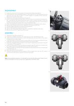
1) Isolate the valve from the line (release the pressure and empty the pipeline). 2) Unlock the union nuts by pressing the lever on the DUAL BLOCK® (26) along the axis and separate it from the union nut (fig. 1). It is also possible to completely remove the block device from the body of the valve. 3) Unscrew the union nuts (13) and extract the body (7). 4) After turning the handle (2) to the position with the three arrows pointing at the three ports (for L-port ball with two arrows facing the ports a and b), extract the insert (1) from the handle (2) and insert the two protrusions in the corresponding...
Open the catalog to page 18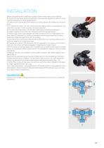
INSTALLATION Before proceeding with installation. please follow these instructions carefully: 1) Check that the pipes to be connected to the valve are aligned in order to avoid mechanical stress on the threaded joints. 2) Check that the DUAL BLOCK® union nut locking device (26) is fitted to the valve body. 3) To release the union nuts (13), axially press the release lever to separate the lock and then unscrew it in the counter-clockwise direction. 4) Unscrew the three union nuts (13) and insert them on the pipe segments. 5) Solvent weld or screw the end connectors (12) onto the pipe ends. 6)...
Open the catalog to page 19All FIP - Formatura Iniezione Polimeri catalogs and technical brochures
 CK/CP DN 12÷15
17 Pages
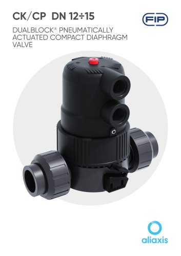 CK/CP DN 12÷15
17 Pages
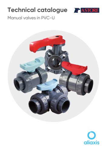 Manual valves in PVC-U
81 Pages
 PIPE ISO-UNI
10 Pages
 FLS
FLS228 Pages
 PP-H
PP-H254 Pages
 PVC-U
PVC-U460 Pages
 PVC-U Fittings
114 Pages
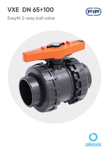 VXE DN 65÷100
13 Pages
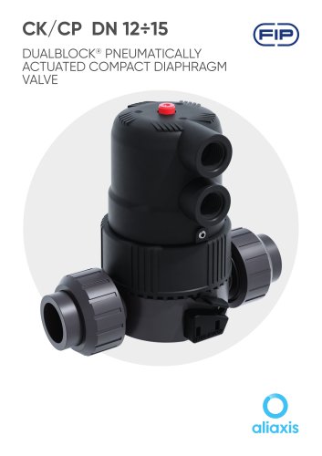 CK/CP DN 12÷15
17 Pages
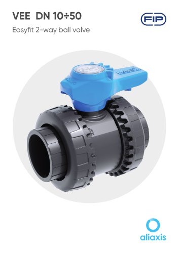 VEE DN 10÷50
15 Pages

Archived catalogs
 PVC-U PRESSURE PIPE
6 Pages
 SXE-SSE 2024
13 Pages
 SXE-SSE DN 10÷50
17 Pages
 VM/RM DN 8÷15
6 Pages
 DK DN
DK DN16 Pages
 VXE EASYFIT DN 65-100
20 Pages
 VEE EASYFIT DN 65-100
16 Pages
 Corporate presentations
12 Pages
 VKD DN 10÷50
16 Pages
 FE DN 40÷200
14 Pages
 Swimming Pool&Spa Solutions
28 Pages
 Chemical Industry Solutions
28 Pages
 Water Treatment solutions
28 Pages
 DK DN 15÷65
16 Pages
 DK/CP DN 15÷20
20 Pages
 SXE-SSE
24 Pages
 VKD Dual Block
6 Pages
 VEE Easyfit Promotional Brochure
16 Pages
 FKOV/FM D355 - D400 ISO-DIN
2 Pages
 VXE Easyfit Promotional Brochur
16 Pages
 PVC-U Manual Valves
246 Pages
 New VKD Ball Valve Dual Block
14 Pages
 PP-H (100) System
198 Pages
 C-PVC TemperFIP 100 System
165 Pages
 PVDF System
141 Pages
 Variable Area Flowmeters
14 Pages
 MAGNUM System and Clamp Saddles
12 Pages
 DK DIALOCK 2017
12 Pages

