


- Company
- Products
- Catalogs
- News & Trends
- Exhibitions
PVC-U
PVC-U
PVC-U, developed in 1930, is a versatile plastic known for its thermal stability, chemical resistance, and mechanical strength. It is economically advantageous for transporting corrosive fluids and water.
PVC-U products comply with ISO 14001 and ISO 9001, and adhere to standards like ANSI B16.5, ASTM D1784, and EN ISO 1452-2, ensuring safety and compatibility.
PVC-U systems are approved by organizations such as ABS, ACS France, and WRAS, confirming their suitability for potable water and maritime applications.
PVC-U offers thermal resistance (0-60°C), low surface roughness, chemical and abrasion resistance, and is non-conductive, reducing condensation and heat loss.
Solvent welding involves joining PVC-U pipes using adhesives. Key steps include cutting, cleaning, applying solvent cement, and ensuring proper insertion and drying times.
Setting times for solvent cement vary with temperature: 5-10 minutes above 10°C, 15-20 minutes below 10°C. Repair joints require 1 hour per atm of pressure, and pressure-tested joints need 24 hours.
Instructions for threaded and flanged joints include using PTFE sealing tape and ensuring proper seal and installation with gaskets and cross-wise bolt tightening.
References include EN ISO 15493 and DIN 8061/62 for construction and testing. Recommendations cover solvent cement use and handling precautions.
Avoid threaded joints in critical applications and using materials like hemp for sealing.
Tables provide dimensions and specifications for PVC-U pressure pipes, including size ranges, pressures, and temperature ranges.
Support clips prevent flexing, with distances varying by material, SDR, temperature, and fluid density. ISO-UNI fittings are rated for PN 16 at 20°C.
Fittings are made from PVC-U with EPDM or FKM seals, complying with international standards.
Regression coefficients for PVC-U are provided, with pressure variations discussed for chemically resistant materials.
Various fittings like elbows and reducers are detailed with dimensions and codes.
Specifications for O-Rings and union components are provided for different series.
Reducers connect pipes of different diameters while maintaining pressure ratings.
Specifications for DUAL BLOCK® 2-way ball valves include materials, pressure, and temperature ranges, with detailed assembly and installation instructions.
Valves are made from PVC-U with EPDM or FKM seals, designed for PN 16 at 20°C.
Valves consist of components like handle inserts and union nuts, with an exploded view provided.
Step-by-step instructions emphasize safety and proper alignment.
Guidance on aligning pipes and securing valves is provided.
Accessories enhance valve functionality, including handle block kits and actuator installation kits.
Pressure variation and flow characteristics are detailed with graphs and coefficients.
Warnings include avoiding volatile liquids and sudden closing operations.
Specifications for DUAL BLOCK® regulating ball valves include flow coefficients and torque requirements.
Flow rate and operating torque are discussed, emphasizing qualified personnel for maintenance.
Dimensions for various valve models are listed with connection types and codes.
Instructions highlight the importance of alignment and proper engagement of the DUAL BLOCK® system.
Materials like PVC-U and PTFE are detailed for valve components.
Pressure variations with temperature are outlined, with recommendations for non-water fluids.
The TKD DUAL BLOCK® ball valve features ergonomic design and compatibility with actuators.
Specifications and instructions for DUAL BLOCK® 3-way ball valves include configurations, components, and installation guidelines.
Valves are available in L bore and T bore configurations, designed for PN 16.
Key components include handles, stems, and O-rings, with an exploded view provided.
Instructions emphasize careful handling and lubrication of components.
Guidelines focus on pipe alignment and securing union nuts.
Accessories enhance valve functionality, including handle block kits and actuator modules.
Warnings include avoiding sudden maneuvers and protecting valves from accidental operations.
The VXE Easyfit 2-way ball valve offers easy maintenance and customization options.
Specifications and instructions for Easyfit 2-way ball valves highlight features, customization, and technical data.
Features include a customizable tag holder and PTFE ball seat system.
Pressure variation and flow coefficients are detailed.
Dimensions for various valve models are provided with specifications.
Step-by-step instructions emphasize proper installation and handling.
Details on available accessories like the Easytorque kit are provided.
Precautions for using certain chemicals and testing methods are outlined.
Specifications for Easyfit 2-way ball valves include dimensions, pressure ratings, and material compatibility.
Various valve types and features are detailed, including the Easyfit system.
Accessories like end connectors and hose adaptors are listed.
Procedures for installation and maintenance emphasize alignment and stress avoidance.
Warnings include avoiding volatile liquids and sudden closing actions.
Technical data includes operating torque and pressure variation graphs.
The Easyfit VEE valves feature a customizable labeling system.
Specifications and instructions for Easyfit True Union ball and spring check valves include materials, components, and customization options.
Valves are made from PVC-U, compatible with water and food substances, and comply with European Directive 2014/68/EU.
Key components include a transparent PVC plug and Easyfit quick release handle.
Valves feature a customizable labeling system for identification.
Steps emphasize alignment, lubrication, and careful handling.
Instructions include pipe alignment and solvent welding or screwing end connectors.
Pressure variation and flow coefficients are detailed.
Dimensions for various valve models and configurations are provided.
Warnings include contacting the service center for volatile liquids and avoiding sudden closures.
Specifications and instructions for Easyfit spring check valves and butterfly valves include technical specifications, component details, and procedures.
Multiple series of Easyfit spring check valves are listed with dimensions and codes.
Valves consist of components like union nuts and valve bodies, with materials detailed.
Disassembly and assembly instructions include using the Easyfit handle for tightening.
Accessories like end connectors and the Easyfit multifunctional handle are described.
Warnings include avoiding compressed air for testing and ensuring proper pipe support.
Specifications for butterfly valves include disk, stem, and seal materials, pressure ratings, and control options.
Specifications for butterfly valves include compatibility with actuators and gearboxes, with sizes ranging from DN 40 to DN 400.
The valve can be equipped with standard pneumatic or electric actuators.
The valve features a customizable Labelling System for easy label application.
An exploded view of valve components is provided, listing materials.
Steps emphasize lubricating rubber seals and avoiding mineral oils.
Instructions include ensuring proper clearance and coupling distances.
Technical data includes pressure variation, flow coefficients, and operating torque.
Recommendations include supporting valves adequately and avoiding sudden closures.
Specifications and instructions for butterfly valves include technical data, component lists, and procedures.
Specifications for different valve models include dimensions, pressure ratings, and materials.
Disassembly and assembly instructions are provided for valve sizes DN 40 to DN 400.
Valves are compatible with ISO-DIN and ANSI standards.
Exploded views and component lists are provided for different valve sizes.
Accessories like the LS Quick Kit and actuator mounting flanges are described.
The FK valve features a customizable labelling system.
Instructions include lubricating and inserting the disk into the liner.
Guidelines include ensuring sufficient clearance and checking coupling distances.
Instructions for installing the valve between flanged stubs are provided.
Instructions for tightening stud-bolts are provided.
The handle allows for 0°-90° operation with a stop lock.
Warnings include supporting valves adequately and avoiding sudden closures.
Features a connection system for various joints and optimized fluid dynamics.
Specifications include size range, nominal pressure, and temperature range.
Pressure variation and Kv100 flow coefficient values are provided.
Dimensions for various valve models and available accessories are provided.
Valves require adequate support, with mounting plates available for installation.
The DIALOCK® DK valve can be customized with a white PVC plate.
Components like the transparent protection cap and O-Ring are listed.
Instructions emphasize aligning and lubricating parts.
Instructions include ensuring pipes are aligned to avoid stress.
The DK valve features a DIALOCK® handwheel locking system.
The DKL version includes a handwheel stroke control system.
Designed for abrasive fluids, featuring a handwheel control and diaphragm seal.
Technical data includes pressure variation and Kv100 flow coefficient values.
Regular checks of the diaphragm condition are advised.
Features corrosion-proof components and a CDSA system for pressure distribution.
Specifications for valves include diaphragm valves and sediment strainers.
Features include an ergonomic handwheel and adjustable torque limiter.
Pressure variation and Kv100 flow coefficient tables are provided.
Dimensions and codes for various valve models are provided.
Instructions emphasize checking diaphragm conditions and proper lubrication.
Valves can be installed in any position, ensuring no leaks occur.
Designed for laboratory applications with a compact design.
Used for fluid regulation, characterized by its small size.
Limits solid particle passage with a strainer that can be cleaned or replaced.
References to international standards for construction and testing are provided.
Specifications and procedures for check valves, air release valves, foot valves, and wafer check valves are provided.
Designed for one-directional fluid flow with a weighted PVC piston.
Eliminates air from pipes and functions as a vacuum breaker.
Allows fluid passage in one direction with minimal pressure loss.
Designed for installation between stubs and flanges.
Valves should be installed by qualified personnel, ensuring proper alignment and sealing.
Specifications for wafer check valves include material and standards.
Kv100 flow coefficient values are provided for different nominal diameters.
Key requirements include ensuring a straight pipe section before and after the valve.
Valves are constructed according to EN ISO standards.
Dimensions for various valve sizes are provided.
Installation by qualified personnel is emphasized, with testing before full operation.
Specifications and procedures for the SV relief valve are provided.
Specifications include construction, size range, and nominal pressure.
The valve is suitable for water and harmless fluids.
Detailed dimensions for different valve sizes are provided.
Exploded view and list of components are provided.
The valve can be installed in any position, ensuring flow direction matches the arrow.
Instructions for calibrating the trip threshold are provided.
Operations on equipment under pressure must be conducted safely.
A list of abbreviations used in the document is provided.
Catalog excerpts

Technical catalogue Manual valves, pipe and fittings in PVC-U
Open the catalog to page 1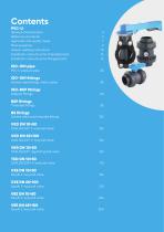
Contents PVC-U General characteristics Reference standards Approvals and quality marks Main properties Solvent welding instructions Installation instructions for threaded joints Installation instructions for flanged joints ISO-UNI pipe PVC-U pressure pipe ISO-UNI fittings Solvent weld fittings, metric series ISO-BSP fittings Adaptor fittings Threaded fittings Solvent weld and threaded fittings DUAL BLOCK® 2-way ball valve DUAL BLOCK® 2-way ball valve DUAL BLOCK® regulating ball valve DUAL BLOCK® 3-way ball valve Easyfit 2-way ball valve Easyfit 2-way ball valve Easyfit 2-way ball valve Easyfit...
Open the catalog to page 3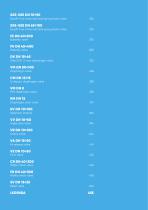
Easyfit True Union ball and spring check valve Easyfit True Union ball and spring check valve 274 DIALOCK® 2-way diaphragm valve 332 Compact diaphragm valve 358 Mini diaphragm valve 368 Diaphragm cock valve 374 Angle seat valve 394 Wafer check valve 430 Wafer check valve 438
Open the catalog to page 4
Developed in 1930 in Germany, PVC-U (rigid polyvinyl chloride - unplasticized) is obtained through the polymerization of a vinyl chloride monomer. The presence of chlorine in the PVC-U molecule results in a high performance resin, in terms of thermal stability and chemical and mechanical resistance, up to temperatures of 60° C. The different formulations obtained by adding suitable additives and stabilizers render the PVC-U the most versatile of all plastic materials, allowing it to be adapted to many applications involving fluids under pressure. PVC-U represents one of the more economic solutions...
Open the catalog to page 5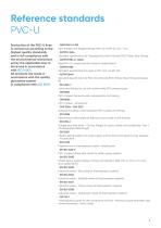
Production of the PVC-U lines is carried out according to the highest quality standards and in full compliance with the environmental restrictions set by the applicable laws in force and in accordance with ISO 14001. All products are made in accordance with the quality guarantee system in compliance with ISO 9001. Pipe, flanges and flanged fittings-NPS 1/2 to NPS 24 mm / inch Standard Specification for Threaded Poly Vinyl Chloride (PVC) Plastic Pipe Fittings Rigid PVC-U compounds (for industrial applications). Standard specification for pipes in PVC, Sch. 40-80-120 Standard Specification for...
Open the catalog to page 7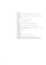
Pipe threads where pressure-tight joints are not made on the threads Plastics piping systems for water supply, and for drains and sewers under pressure - Polyethylene Industrial valves - Part-turn actuator couplings Fittings with pressure-tight threaded joints PVC-U pipes and fittings Dimensions and tolerances, metric series Thermoplastics valves - pressure test methods and requirements Thermoplastic piping systems for fluids under pressure -flange adapters and loose backing flanges- Mating dimensions Tapered pipe threads PVC-U pipes PVC-U pipe fittings for water supply systems Solvent welding...
Open the catalog to page 8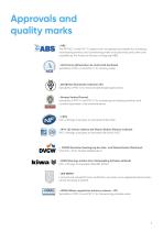
Approvals and quality marks l ABS The FIP PVC-U and PVC-C systems are recognised as suitable for conveying and treating sanitary and conditioning water on board ships and other units classified by the American Bureau of Shipping (ABS) l ACS France (Attestation de conformité Sanitaire) Suitability of PVC-U and PVC-C for drinking water l BSI (British Standards Institution UK) Suitability of PVC-U for food and beverage applications l Bureau Veritas (France) Suitability of PVC-U and PVC-C for conveying and treating sanitary and conditioning water in the maritime sector l CSTB PVC-U fittings and pipes...
Open the catalog to page 9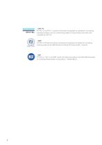
FIP PVC-U and PVC-C systems have been recognised as suitable for conveying, □ NVGL treating domestic and air conditioning waters on board ships and other units classified by DNV-GL • NIZP FIP PVC-U fittings and valves have been recognised as suitable for conveying drinking water by the NIZP (National Institute of Public Health - Poland) FIP PVC-U , PVC-C and PPH valves are listed according to the NSF/ANSI Standard 61 -Drinking Water System Components - Health Effects
Open the catalog to page 10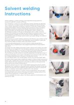
Solvent welding Instructions Solvent welding, or cement jointing, is the longitudinal joining system for connecting rigid PVC-U pipes and fittings. The "cementing" is carried out using adhesives/cements obtained by dissolving PVC-U polymer in a solvent mixture. This solvent liquefies the walls of the pipe and/or fitting, allowing the constituent material to chemically combine and be subsequently welded. Chemical welding allows permanent joints be achieved possessing chemical and mechanical strength characteristics identical to those of the pipes and fittings joined. The adhesives/solvent cements...
Open the catalog to page 12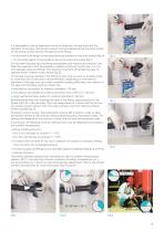
It is advisable to use an applicator/brush of dimension not less than half the diameter of the pipe. The solvent cement must be applied along the entire length of the joining surface of both the pipe and the fitting: • for the entire joint length of the pipe previously marked on the outer surface (fig. 6) • for the entire depth of the socket as far as the internal shoulder (fig.7) 6) Fully insert the pipe into the fitting immediately and without any rotation. Only after this operation will it be possible to slightly rotate both ends (max. 1/4 of a turn between pipe and fitting). This rotation...
Open the catalog to page 13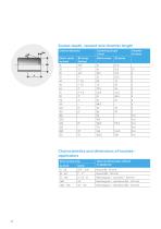
Characteristics and dimensions of brushes-applicators External diameter
Open the catalog to page 14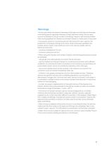
• In the case where the external diameter of the pipe and the internal diameter of the fitting are at opposite extremes of their tolerance values, the dry pipe cannot be inserted in the dry socket of the fitting. Insertion will only be possible after having applied the Cleaner and Solvent Cement to both parts to be joined. • The solvent cement is manufactured from the same PVC resin used for the production of the pipes, fittings and valves. Unless otherwise specified, the solvent cement used on the surfaces to join must also be usable with the following tolerances: • When using the Cleaner and...
Open the catalog to page 15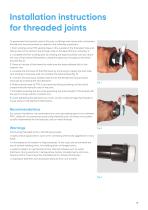
Installation instructions for threaded joints To guarantee the hydraulic seal of the joint on fittings and valves with a threaded female end, we recommend you perform the following operations: 1. Start winding some PTFE sealing tape on the outside of the threaded male end, taking care not to obstruct the through-hole on the pipe, fitting or valve (fig. 1); 2. Complete the first winding layer by winding the tape clockwise until you reach the root of the thread. Remember to keep the tape taut throughout the entire process (fig. 2); 3. Press on the tips of the thread to make sure the tape adheres...
Open the catalog to page 17All FIP - Formatura Iniezione Polimeri catalogs and technical brochures
 CK/CP DN 12÷15
17 Pages
 CK/CP DN 12÷15
17 Pages
 Manual valves in PVC-U
81 Pages
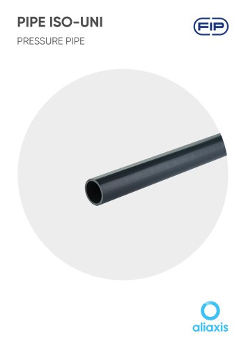 PIPE ISO-UNI
10 Pages
 FLS
FLS228 Pages
 PP-H
PP-H254 Pages
 PVC-U Fittings
114 Pages
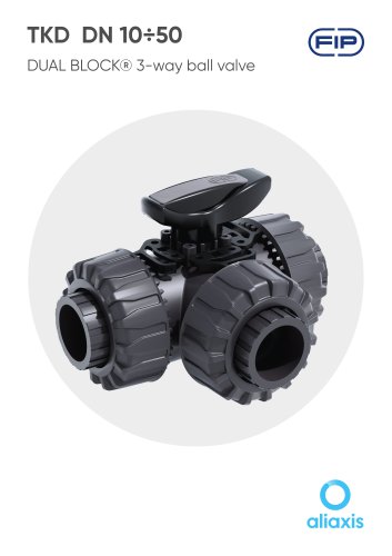 TKD DN 10÷50
19 Pages
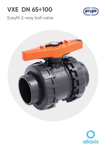 VXE DN 65÷100
13 Pages
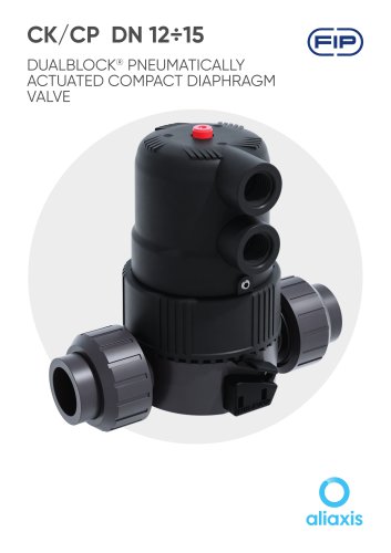 CK/CP DN 12÷15
17 Pages
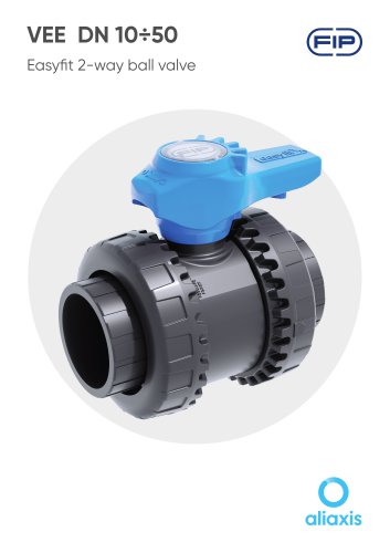 VEE DN 10÷50
15 Pages
Archived catalogs
 PVC-U PRESSURE PIPE
6 Pages
 SXE-SSE 2024
13 Pages
 SXE-SSE DN 10÷50
17 Pages
 VM/RM DN 8÷15
6 Pages
 DK DN
DK DN16 Pages
 VXE EASYFIT DN 65-100
20 Pages
 VEE EASYFIT DN 65-100
16 Pages
 Corporate presentations
12 Pages
 VKD DN 10÷50
16 Pages
 FE DN 40÷200
14 Pages
 Swimming Pool&Spa Solutions
28 Pages
 Chemical Industry Solutions
28 Pages
 Water Treatment solutions
28 Pages
 DK DN 15÷65
16 Pages
 DK/CP DN 15÷20
20 Pages
 SXE-SSE
24 Pages
 VKD Dual Block
6 Pages
 VEE Easyfit Promotional Brochure
16 Pages
 FKOV/FM D355 - D400 ISO-DIN
2 Pages
 VXE Easyfit Promotional Brochur
16 Pages
 PVC-U Manual Valves
246 Pages
 New VKD Ball Valve Dual Block
14 Pages
 PP-H (100) System
198 Pages
 C-PVC TemperFIP 100 System
165 Pages
 PVDF System
141 Pages
 Variable Area Flowmeters
14 Pages
 MAGNUM System and Clamp Saddles
12 Pages
 DK DIALOCK 2017
12 Pages

