
- Catalogs
- FIP - Formatura Iniezione Polimeri
- PP-H (100) System


- Company
- Products
- Catalogs
- News & Trends
- Exhibitions
PP-H (100) System

1 / 198 PagesView full catalog
PP-H (100) System
Product catalog summary
Introduction
FIP, part of the Aliaxis Group, has been manufacturing injection-moulded valves and fittings from thermoplastic materials since 1954. It is the largest European manufacturer of valves, adhering to ISO 9001 and ISO 14001 standards.
FIP, part of the Aliaxis Group, has been manufacturing injection-moulded valves and fittings from thermoplastic materials since 1954. It is the largest European manufacturer of valves, adhering to ISO 9001 and ISO 14001 standards.
PP-H System Overview
The PP-H system includes pipes, fittings, and valves made from homopolymer polypropylene (PP-H 100), designed for industrial fluid conveyance under pressure and temperatures up to 100°C. It complies with DIN 8077-8078, DIN 16962 standards, and is approved by DIBt for industrial use.
The PP-H system includes pipes, fittings, and valves made from homopolymer polypropylene (PP-H 100), designed for industrial fluid conveyance under pressure and temperatures up to 100°C. It complies with DIN 8077-8078, DIN 16962 standards, and is approved by DIBt for industrial use.
Main Properties and Characteristics
- Chemical Resistance: Excellent resistance to chemicals, especially halogens and alkaline solutions.
- Thermal Stability: Optimal performance between 10°C and 80°C.
- Durability: High circumferential breaking strength (MRS ≥ 10.0 MPa at 20°C).
Product Range
Includes ball valves, butterfly valves, diaphragm valves, check valves, sediment strainers, and fittings for socket and butt welding.
Includes ball valves, butterfly valves, diaphragm valves, check valves, sediment strainers, and fittings for socket and butt welding.
General Characteristics of Polypropylene
Polypropylene is a partially crystalline thermoplastic resin with mechanical, physical, and thermal properties. It is available in PP-Homopolymer (PP-H), PP-Block Copolymer (PP-B), and PP-Random Copolymer (PP-R) forms.
Polypropylene is a partially crystalline thermoplastic resin with mechanical, physical, and thermal properties. It is available in PP-Homopolymer (PP-H), PP-Block Copolymer (PP-B), and PP-Random Copolymer (PP-R) forms.
Manufacturing and Quality Assurance
PP-H products are manufactured in Europe, adhering to high-quality standards and environmental regulations, certified under ISO 9001.
PP-H products are manufactured in Europe, adhering to high-quality standards and environmental regulations, certified under ISO 9001.
Main Properties of Latest Generation Homopolymeric Resins
- Longevity: High Minimum Required Strength (MRS) of 10.0 MPa.
- Optimal Thermal Stability: Effective at intermediate temperatures (40-70°C).
- Enhanced Chemical Resistance: Additives provide resistance to detergents.
Physical Characteristics of PP-H
- Density: 0.9 g/cm³
- Melt Flow Index: 0.3-0.5 g/(10min)
- Flexural Modulus: 1300 N/mm²
- IZOD Notched Impact Strength at 23°C: 150 J/m
- Tensile Elongation at Break: >50%
- Rockwell Hardness: 100 R
- Tensile Strength: 33 N/mm²
- VICAT Softening Point: 142°C
- HDT Bending Temperature: 91°C
- Thermal Conductivity at 20°C: 0.22 W/(m°C)
- Coefficient of Linear Thermal Expansion: 16 x 10-5 m/(m°C)
- Limiting Oxygen Index: 17.5%
Normative References
- EN ISO 15494: Systems of components in PP-H for industrial applications.
- DIN 8077-8078: PP-H pipes, metric series dimensions.
- DIN 16962: PP-H fittings for socket and butt welding, dimensions.
- UNI 8318: PP-H pipes for fluid pressure systems, types, and dimensions.
- DVS 2207-11: Socket and butt welding of PP-H components.
- DVS 2202-1: Imperfections of PP-H welding joints, features, descriptions, and evaluation.
- DVS 2208-1: Machines and devices for heated tool welding.
- ASTM D 4101-06: Polypropylene compounds according to PP0110B56000 classification.
Approvals and Quality Marks
- DIBt: Suitability of PP-H for transport of industrial fluids.
- GOST-R: FIP PP-H valves certified according to Russian safety and quality regulations.
- Ukrainian Certification: FIP PP-H valves certified for safety, hygiene, and quality.
- TA-Luft: FIP PP-H valves tested and certified for air quality control.
Benefits of PP-H
- Application range of 0-100°C with high flow coefficients due to smooth internal walls.
- Constant pressure drops over time and low risk of downtimes due to deposits.
- Minimal material release into conveyed fluids and excellent chemical resistance.
- Lower costs due to longer working life and reduced installation and transport costs.
- Non-conductive, eliminating galvanic corrosion issues, and physiologically safe.
Specifications
PP-H pipes are available in sizes from 20 mm to 400 mm, designed for working pressure classes PN 6 and PN 10 at 20°C. Jointing techniques include socket fusion or butt welding, compliant with DIN 8077/8078, UNI 8318, and EN ISO 15494 standards.
PP-H pipes are available in sizes from 20 mm to 400 mm, designed for working pressure classes PN 6 and PN 10 at 20°C. Jointing techniques include socket fusion or butt welding, compliant with DIN 8077/8078, UNI 8318, and EN ISO 15494 standards.
Technical Data
Includes nominal outside diameter (d), nominal internal diameter (DN), nominal pressure (PN), standard dimension ratio (SDR), wall thickness (s), and minimum required strength (MRS) for water at 20°C for 50 years.
Includes nominal outside diameter (d), nominal internal diameter (DN), nominal pressure (PN), standard dimension ratio (SDR), wall thickness (s), and minimum required strength (MRS) for water at 20°C for 50 years.
Pressure/Temperature Ratings
Regression curves indicate pressure variation with temperature for water and non-hazardous fluids. Ratings are provided for different SDR values and time durations (5, 10, 25, and 50 years).
Regression curves indicate pressure variation with temperature for water and non-hazardous fluids. Ratings are provided for different SDR values and time durations (5, 10, 25, and 50 years).
Fittings and Jointing
FIP offers a range of fittings for socket fusion and threaded connections, compliant with DIN 16962, UNI ISO 228/1, DIN 2999, and BS 21 standards.
FIP offers a range of fittings for socket fusion and threaded connections, compliant with DIN 16962, UNI ISO 228/1, DIN 2999, and BS 21 standards.
Disclaimer
Data is provided in good faith, but FIP does not accept liability for data not covered by recognized international standards. FIP reserves the right to modify products.
Data is provided in good faith, but FIP does not accept liability for data not covered by recognized international standards. FIP reserves the right to modify products.
Procedures
Socket welding involves heating pipe and fitting surfaces to fuse them together using manual or automatic heating devices. The pipe must be cut, chamfered, and cleaned before welding.
Socket welding involves heating pipe and fitting surfaces to fuse them together using manual or automatic heating devices. The pipe must be cut, chamfered, and cleaned before welding.
Standards and Norms
Fittings and components adhere to DIN standards, ensuring compatibility and pressure rating compliance.
Fittings and components adhere to DIN standards, ensuring compatibility and pressure rating compliance.
Recommendations
Ensure proper alignment and support of welded elements for at least 15 seconds post-insertion. Allow the joint to cool naturally without forced air or water immersion.
Ensure proper alignment and support of welded elements for at least 15 seconds post-insertion. Allow the joint to cool naturally without forced air or water immersion.
Key Data from Tables
Tables provide dimensions and specifications for various fittings, including diameter (d), height (H), and other critical measurements.
Tables provide dimensions and specifications for various fittings, including diameter (d), height (H), and other critical measurements.
Butt Welding Procedure
Involves joining two elements by heating their surfaces until fusion and then pressing them together. Key conditions include maintaining ambient temperatures between +5°C and +40°C and ensuring the fusion temperature is between 200 and 220°C.
Involves joining two elements by heating their surfaces until fusion and then pressing them together. Key conditions include maintaining ambient temperatures between +5°C and +40°C and ensuring the fusion temperature is between 200 and 220°C.
Preparation for Welding
Ensure the heating element is clean and functioning correctly. Surfaces must be cleaned of dirt and grease using recommended detergents.
Ensure the heating element is clean and functioning correctly. Surfaces must be cleaned of dirt and grease using recommended detergents.
Planing of Edges
Edges must be planed to ensure proper parallelism and remove oxide films. The gap between edges should not exceed 0.5 mm.
Edges must be planed to ensure proper parallelism and remove oxide films. The gap between edges should not exceed 0.5 mm.
Technical Document Summary
Specifications and Procedures
Outlines the procedure for butt fusion welding of pipes and fittings using contact heating elements. Emphasizes ensuring planarity of joining surfaces and removing oxide layers before welding.
Outlines the procedure for butt fusion welding of pipes and fittings using contact heating elements. Emphasizes ensuring planarity of joining surfaces and removing oxide layers before welding.
Key Parameters
- Pressure during contact and preheating should be 0.1 N/mm².
- The heating element removal must be quick to prevent excessive cooling.
- Cooling time should be at least equal to the welding time.
- Pressure during contact and preheating should be 0.1 N/mm².
- The heating element removal must be quick to prevent excessive cooling.
- Cooling time should be at least equal to the welding time.
Quality Control
Describes methods for evaluating the quality of the welded joint: non-destructive and destructive tests. Visual inspections ensure the weld bead is uniform and free of porosity.
Describes methods for evaluating the quality of the welded joint: non-destructive and destructive tests. Visual inspections ensure the weld bead is uniform and free of porosity.
Visual Inspection Specifications
- The weld bead should be uniform around the joint circumference.
- The notch between the weld beads must be above the outer diameter of the welded elements.
- The outer surface should be free of porosity and contamination.
- No visible surface break-up should be present.
- The weld bead surface should not be overly shiny, indicating overheating.
- Axial misalignment of welded parts should not exceed 10% of their thickness.
Main Defects Identified by Visual Inspection
- Irregular weld bead path around the pipe circumference.
- Reduced size of the weld bead.
- Excessively deep notch in the center of the bead.
- Inclusions on the weld bead surface.
- Porosity of the weld bead.
- Excessive shine on the weld bead surface.
- Misalignment exceeding 10% of the pipe and fitting thickness.
Probable Causes of Defects
- Insufficient preparation of welding ends leading to uneven heat distribution.
- Incorrect adjustment of welding parameters (temperature, pressure, time).
- Temperature or pressure values lower than recommended.
- Inadequate cleaning of welding ends.
- Welding in excessively humid conditions.
- Overheating during welding.
- Incorrect centering or excessive ovality of pipes.
Compatibility and Safety Factors
- PP-H components can be welded with PPR and PPB components if MFI compatibility is verified.
- Differences in MRS values between PP-H and PPR require specific safety factors.
- SDR (Standard Dimension Ratio) and Series of thicknesses S are crucial for determining nominal pressure values.
- According to EN-ISO 15494-1, safety factors and SDR/Series determine the reference nominal pressure value PN.
VK DualBlock® Ball Valve Features
- Size range from 16 mm to 63 mm, with various connection options.
- Maximum working pressure of 10 bar at 20°C.
- Patented DualBlock® system ensures nut position under severe conditions.
- Easy removal and replacement of O-rings and ball seats.
- SEAT-STOP design allows micro-adjustment of ball seal.
- Pipeline can be disconnected downstream without leakage when closed.
- Manual version with ergonomic handle and optional locking device.
- Compatible with electric or pneumatic actuators using standard ISO 5211 mounting kits.
Overview The document provides technical specifications and details for the VK DualBlock® 2-way ball valve, designed by FIP to meet high standards in thermoplastic valve design. The valve is suitable for severe industrial applications, ensuring reliable and trouble-free service.
Specifications
- Size Range: DN 65 mm to DN 100 mm.
- Pressure Rating: Maximum working pressure of 10 bar at 20°C.
- Material: Made from polypropylene homopolymer (PP-H) and high impact PVC (HIPVC).
- Connection Types: Socket or butt welding, with options for fixed flanges.
Design Features
- Easy removal of the valve body for quick replacement of O-rings and ball seats without tools.
- New seat and seal design with micro-adjustment capabilities.
- Manual operation with an ergonomic handle, featuring a locking device and flow throttling.
- Compatibility with manual gearboxes and pneumatic/electric actuators via a standard ISO 5211 F07 flange.
Standards Compliance
- Socket fusion: DIN 16962, compatible with EN ISO 15494, DIN 8077, UNI 8318.
- Flanged couplings: ISO 2084, UNI EN 1452, DIN 8063, ASA ANSI B.16.5 150.
Technical Data
- Pressure/Temperature Rating: Suitable for water and non-hazardous fluids, with a 25-year safety factor.
- Flow Coefficient (kv100): Defined as the flow rate in liters per minute of water at 20°C with a 1 bar pressure drop.
Accessories The document lists various connectors and accessories compatible with the valve, including long spigot ends for electrofusion or butt welding.
Overview The document provides technical details and installation instructions for the MS kit and VKD manual valve. The MS kit allows the installation of a limit switch-box on the VKD valve to signal its position (open or closed) to a control panel. The kit can be mounted on already installed valves.
Specifications The MS kit is compatible with VKD valves of sizes DN 65 to 100 and d 75 to 110. It supports both mechanical and inductive switches, with specific part numbers for each type. The valve can also be equipped with actuators and reduction gears, using a flange drilled according to ISO 5211 F07 standards.
Installation Procedures The document outlines the steps for installing the valve onto a system, including unscrewing union nuts, solvent welding or screwing end connectors, and positioning the valve. The Dual Block® system is highlighted as a patented mechanism for securing the union nuts in a preset position, ensuring stability even under severe conditions like vibrations or thermal expansion.
Support and Bracketing VKD valves come with integrated supports for easy anchoring. These supports are crucial for handling the valve's weight and operational stresses. The document advises designing systems to accommodate thermal expansion to prevent damage.
Disassembly Instructions Detailed steps are provided for disassembling the valve, including isolating the valve, unlocking and unscrewing union nuts, and removing various components like the handle, screws, and ball. Care is advised to avoid damaging parts during disassembly.
Safety Recommendations The document advises contacting technical services when using volatile liquids like hydrogen peroxide or sodium hypochlorite, as they may cause dangerous pressure increases.
Specifications The document details the specifications of the 3-way ball valve DualBlock® used for diverting or mixing pipeline flows. It covers a size range from d20 mm to d63 mm (R 1/2” to 2”) and can handle a maximum working pressure of 16 bar at 20°C. The valve features a patented DualBlock® system that ensures the nuts remain in position even under severe conditions such as vibration or thermal expansion. It also allows for radial disassembly at all three connection points and offers a T bore ball with an optional L bore.
Procedures The document provides detailed assembly and disassembly procedures for the valve. Key steps include inserting O-rings into their grooves, placing bushes on stems, inserting the ball, and securing components with screws and washers. It emphasizes the importance of using the correct tools and following the sequence to ensure proper assembly and disassembly.
Standards and Recommendations The document advises lubricating rubber seals during assembly but warns against using mineral oils as they can damage EPDM rubber. It also cautions against rapid closure of valves to prevent water hammer and potential pipeline damage.
Components and Materials A comprehensive list of components and materials is provided, including protection caps, handles, screws, washers, and various seals. Materials used include PE, HIPVC, stainless steel, PTFE, PP-H, and EPDM-FPM, among others.
Warnings and Notes Warnings include avoiding rapid valve closure and protecting the valve from accidental operations. Notes suggest lubricating O-rings during assembly and highlight the unsuitability of mineral oils for EPDM rubber.
Additional Features The valve includes a Seat Stop® design for micro-adjustment of ball seals and a handle stop device every 90° with an optional safety block system. It also supports the installation of electric or pneumatic actuators using GR-PP mounting kits with standard ISO 5211 drilling.
Technical Specifications The document provides detailed specifications for various components and materials used in piping systems. Key terms include nominal diameters (d and DN), nominal pressure (PN), and weight (g). Materials such as polypropylene homopolymer (PP-H), high impact PVC (HIPVC), and various elastomers like EPDM and FPM are described.
Procedures and Standards The document outlines procedures for socket fusion and threaded coupling, adhering to standards such as DIN 16962, EN ISO 15494, and UNI-ISO 228/1. It also details the working positions for T and L bore valves, specifying angles for mixing, diverting, and closing.
Pressure and Temperature Ratings Charts and diagrams illustrate the relationship between pressure and temperature, emphasizing the need for pressure reduction in certain conditions. The document specifies a 25-year safety factor for pressure ratings.
Flow and Pressure Loss Flow coefficients (Kv100) are provided, indicating the flow rate in liters per minute at a differential pressure of 1 bar. Pressure loss charts are included for various nominal diameters.
Valve Dimensions and Accessories Dimensions for ball valves with different coupling types are detailed, including metric series and threaded ends. Accessories such as end connectors and actuation modules for pneumatic and electric valves are described, with part numbers and specifications.
Recommendations The document recommends using specific mounting kits for installing actuators and highlights the availability of handle block kits and rotational stroke limiters for precise valve operation.
Specifications The document describes the MSKD limit switch-box, which can be equipped with mechanical or proximity switches to signal the valve position to a control panel. The maximum rotation of the valve is 90°. Installation on a manual valve is possible using the PowerQuick actuation module. The box can be mounted on a TKD valve even if it is already installed.
Technical Data The document provides technical specifications for different models of the MSKD switch-box, including part numbers, switch types (electromechanical and inductive), and electrical parameters such as no-load supply current, voltage drop, operating current, nominal voltage, and operating voltage. It also mentions the endurance and rate of the switches.
Valve Bracketing and Supporting All TKD valves come with integrated supports for easy anchoring. The document emphasizes the importance of supporting valves to withstand weight and operational stresses. It provides specifications for anchoring using standard threaded nuts and highlights the need to accommodate thermal expansion to prevent damage.
Installation Instructions The document outlines detailed installation steps for connecting the valve to the system. It includes checking pipe alignment, unscrewing union nuts, welding or screwing end connectors, and installing the DualBlock® lock nut device. The DualBlock® system ensures the nuts remain secure under severe conditions.
Sealing Adjustment Instructions are provided for adjusting the valve sealing using a removable insert on the handle. The document includes a sequence for tightening the ball carrier to achieve perfect sealing.
Additional Features The TKD valve can be equipped with a handle block device to prevent unauthorized operation. A padlock can also be installed for additional security.
Specifications The FIP ball check valve is designed for unidirectional fluid flow, with a size range from 20 mm to 63 mm. It can withstand a maximum working pressure of 10 bar at 20°C for water. The valve is suitable for liquids with a specific gravity less than 1.20 g/cm³. It features a new seat and seal design with an anti-blowout mechanism and a talc-filled polypropylene ball.
Standards and Compatibility The valve connections comply with DIN 16962 standards and are compatible with pipes adhering to EN ISO 15494, UNI 8318, and DIN 8077 standards.
Installation and Maintenance The valve can be installed on both horizontal and vertical pipelines. It should be aligned with the flow direction indicated by an arrow on the valve body. Maintenance can be performed with the valve body in place, and it is recommended to lubricate rubber seals with suitable oils or greases, avoiding mineral oils that can damage EPDM rubber.
Technical Data The pressure/temperature rating is specified for water and non-hazardous fluids, with a requirement for pressure reduction in other cases. The flow coefficient kv100 is defined as the flow rate in liters per minute of water at 20°C with a 1 bar pressure differential.
Components and Materials The valve consists of several components including the body, ball, collar, lock nut, support, and various seals, primarily made from PP-H (polypropylene) and EPDM or FPM (fluoroelastomer) for seals.
Disclaimer Data provided is in good faith, with no liability for data not covered by recognized international standards. FIP reserves the right to modify the products.
Assembly Instructions
1. Insert the primary liner onto the body.
2. Place O-rings and washers on the bushes.
3. Position O-rings on the shaft, insert the upper bush, and secure with the Seeger ring.
4. Position O-rings on antifriction washers.
5. Insert antifriction washers into disc housings, lubricate the gasket, and place the disc inside the body.
6. Pass the shaft through the body and disc.
7. Position the lower bush from the bottom.
8. Tighten the screw with washers and place the protection cap.
1. Insert the primary liner onto the body.
2. Place O-rings and washers on the bushes.
3. Position O-rings on the shaft, insert the upper bush, and secure with the Seeger ring.
4. Position O-rings on antifriction washers.
5. Insert antifriction washers into disc housings, lubricate the gasket, and place the disc inside the body.
6. Pass the shaft through the body and disc.
7. Position the lower bush from the bottom.
8. Tighten the screw with washers and place the protection cap.
Disassembly Instructions
1. Remove the protection cap and unscrew the screw with washers.
2. Pull out the shaft and disc.
3. Remove the primary liner from the body.
4. Remove the Seeger ring and bushes with the washer.
5. Pull out the lower bush.
6. Remove the O-rings.
1. Remove the protection cap and unscrew the screw with washers.
2. Pull out the shaft and disc.
3. Remove the primary liner from the body.
4. Remove the Seeger ring and bushes with the washer.
5. Pull out the lower bush.
6. Remove the O-rings.
Component List
- Body, Washer, Bush, O-Ring, Shaft, Seeger Ring, etc.
- Materials include PP-GR, Stainless Steel, EPDM or FPM, etc.
- Body, Washer, Bush, O-Ring, Shaft, Seeger Ring, etc.
- Materials include PP-GR, Stainless Steel, EPDM or FPM, etc.
Diaphragm Valve Characteristics
- Manually operated with a non-rising hand-wheel.
- Metal spindle and sleeve for reliability.
- Compact and sturdy design.
- Suitable for liquid and gaseous fluids, especially abrasive media.
- Can be mounted in any position.
- High flow coefficient and reduced pressure losses.
- Modular range with easy diaphragm replacement.
- Standard position indicator.
- Manually operated with a non-rising hand-wheel.
- Metal spindle and sleeve for reliability.
- Compact and sturdy design.
- Suitable for liquid and gaseous fluids, especially abrasive media.
- Can be mounted in any position.
- High flow coefficient and reduced pressure losses.
- Modular range with easy diaphragm replacement.
- Standard position indicator.
Accessories
- Security blocking device.
- Electrical position indicator.
- Alignment plate for DN 15-50 bodies.
- Security blocking device.
- Electrical position indicator.
- Alignment plate for DN 15-50 bodies.
Assembly Instructions
1. Insert the handwheel into the bonnet.
2. Place the compression bearing over the handwheel bushing and secure with a security ring using a liquid thread locker like Loctite.
3. Attach the compressor to the indicator stem and fix it with a pin, ensuring a solid fit.
4. Screw the indicator stem into the handwheel's threaded sleeve, noting the left-hand thread. Align the compressor so that the guide pins match the bonnet grooves.
5. Rotate the compressor into the bonnet until it stops, then screw the diaphragm into the compressor until it stops and back off until the holes align.
6. Place the bonnet with the diaphragm onto the valve body and secure with hexagonal screws, ensuring washers are used and tightened in a cross pattern.
1. Insert the handwheel into the bonnet.
2. Place the compression bearing over the handwheel bushing and secure with a security ring using a liquid thread locker like Loctite.
3. Attach the compressor to the indicator stem and fix it with a pin, ensuring a solid fit.
4. Screw the indicator stem into the handwheel's threaded sleeve, noting the left-hand thread. Align the compressor so that the guide pins match the bonnet grooves.
5. Rotate the compressor into the bonnet until it stops, then screw the diaphragm into the compressor until it stops and back off until the holes align.
6. Place the bonnet with the diaphragm onto the valve body and secure with hexagonal screws, ensuring washers are used and tightened in a cross pattern.
Component Specifications
- Handwheel, Bonnet, Compression Bearing, Security Ring, Indicator Stem, Compressor, Pin, Sealing Diaphragm, Valve Body, Washer, Hexagonal Screw, Protective Cap.
- Materials include PP/glass, POM, brass, stainless steel, EPDM, FPM, PTFE, zinc-plated steel, and PE.
- Handwheel, Bonnet, Compression Bearing, Security Ring, Indicator Stem, Compressor, Pin, Sealing Diaphragm, Valve Body, Washer, Hexagonal Screw, Protective Cap.
- Materials include PP/glass, POM, brass, stainless steel, EPDM, FPM, PTFE, zinc-plated steel, and PE.
Product Features
- Compact design suitable for tight spaces.
- Position indicator and floating diaphragm suspension.
- Adjustable travel stop and easy diaphragm replacement.
- Non-corrosive internal components and sealed handwheel.
- Rising handwheel during valve opening.
- Compact design suitable for tight spaces.
- Position indicator and floating diaphragm suspension.
- Adjustable travel stop and easy diaphragm replacement.
- Non-corrosive internal components and sealed handwheel.
- Rising handwheel during valve opening.
Technical Data
- Pressure/temperature rating for water and harmless fluids.
- Flow coefficient kv100 indicates the flow rate with a one-bar pressure differential.
- Available in various versions with socket fusion and threaded couplings.
- Pressure/temperature rating for water and harmless fluids.
- Flow coefficient kv100 indicates the flow rate with a one-bar pressure differential.
- Available in various versions with socket fusion and threaded couplings.
Installation and Adjustment
- The valve can be installed in any position and direction.
- Ensure no leaks between the diaphragm and valve body during startup.
- The closure limiter allows for limiting diaphragm movement to prevent excessive compression or ensure a minimum fluid flow.
- Factory settings ensure sealing, with adjustments possible if necessary.
- The valve can be installed in any position and direction.
- Ensure no leaks between the diaphragm and valve body during startup.
- The closure limiter allows for limiting diaphragm movement to prevent excessive compression or ensure a minimum fluid flow.
- Factory settings ensure sealing, with adjustments possible if necessary.
Technical Specifications The document provides detailed specifications for various materials and components used in sediment strainers, including PP-H (Polypropylene Homopolymer), PPG (Glass Fiber Reinforced Polypropylene), EPDM (Ethylene Propylene Diene Monomer), and FPM (Fluoroelastomer). It also includes dimensions and pressure ratings for different components.
Flow Coefficient (Kv100) Kv100 is defined as the flow rate in liters per minute of water at 20°C that results in a pressure drop of 1 bar across a fully open valve. The document provides Kv100 values for different valve sizes.
Pressure/Temperature Ratings The document outlines the pressure and temperature ratings for water and non-hazardous fluids, emphasizing the chemical resistance of materials. It notes that a reduction in nominal pressure (PN) is required for other cases, with a safety factor considered over 25 years.
Installation Instructions The sediment strainer can be installed in any position, ensuring the flow direction aligns with the arrow on the body and the filter element is oriented downwards. The document provides step-by-step instructions for installation using union nuts and heat fusion for different configurations (Figures A, B, and C).
Disassembly and Maintenance Instructions for disassembly include isolating the strainer from the flow, unscrewing components, and removing seals and screens. Maintenance recommendations include lubricating rubber seals with appropriate oils and greases, avoiding mineral oils due to their aggressive nature towards ethylene-propylene rubber.
Assembly Instructions Reassembly involves fitting O-rings, securing components with lock nuts and retaining rings, and ensuring proper alignment and sealing of the filter screen and housing.
Dimensional Data The document provides detailed dimensional data for various strainer models, including maximum dimensions, pressure ratings, and weight for different nominal diameters (DN).
Specifications The document provides technical specifications for FIP check valves made from homopolymer polypropylene (PP-H). These valves allow fluid flow in one direction only, with a size range from 20 mm to 90 mm. They can withstand a maximum working pressure of 10 bar at 20°C and a maximum temperature of 100°C. Maintenance can be performed without removing the valve body from the pipeline.
Components and Materials The check valve consists of various components such as the body, screen, bonnet, O-ring seal, and union nut, primarily made from PP-H and EPDM/FPM materials. Spare parts are indicated in the component list.
Installation Procedures Check valves can be installed on horizontal or vertical pipelines. The piston housing must be upright to function correctly. The installation involves unscrewing union nuts, heat fusing valve end connectors, positioning the valve, and tightening the nuts. Detailed installation instructions are provided in the manual.
Technical Data The document includes pressure/temperature ratings for water and non-hazardous fluids, with a flow coefficient Kv100 indicating the flow rate through the valve at a specified pressure differential. Pressure loss charts and minimum pressure requirements for piston operation are also provided.
Maintenance and Disassembly Maintenance can be performed with the valve installed. Disassembly involves isolating the valve, unscrewing components, and removing seals and pistons as needed. Detailed steps for disassembly are outlined in the document.
Standards and Compliance The valves comply with DIN 16962 standards and can be coupled with pipes meeting EN ISO 15494, UNI 8318, and DIN 8077 standards. The document notes that data is provided in good faith, with no liability for data not covered by recognized international standards.
See more
All FIP - Formatura Iniezione Polimeri catalogs and technical brochures
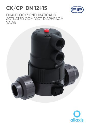 CK/CP DN 12÷15
17 Pages
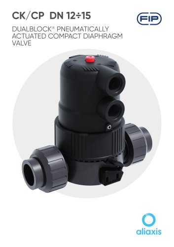 CK/CP DN 12÷15
17 Pages
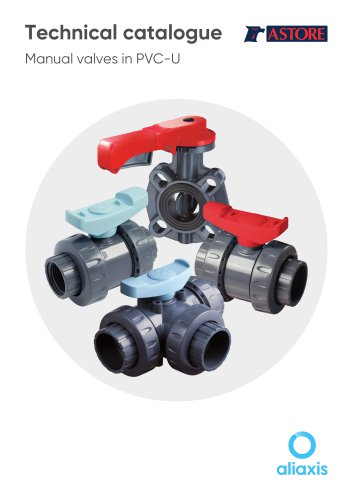 Manual valves in PVC-U
81 Pages
 PIPE ISO-UNI
10 Pages
 FLS
FLS228 Pages
 PP-H
PP-H254 Pages
 PVC-U
PVC-U460 Pages
 PVC-U Fittings
114 Pages
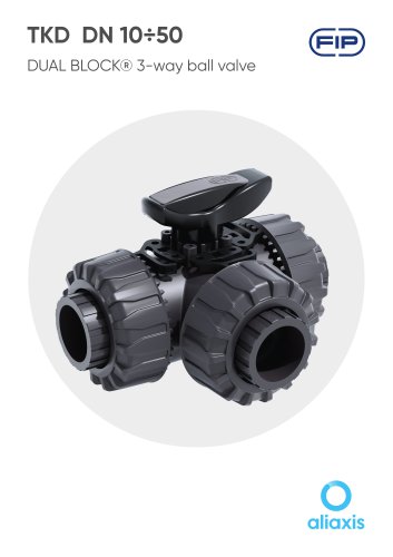 TKD DN 10÷50
19 Pages
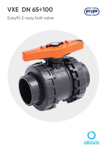 VXE DN 65÷100
13 Pages
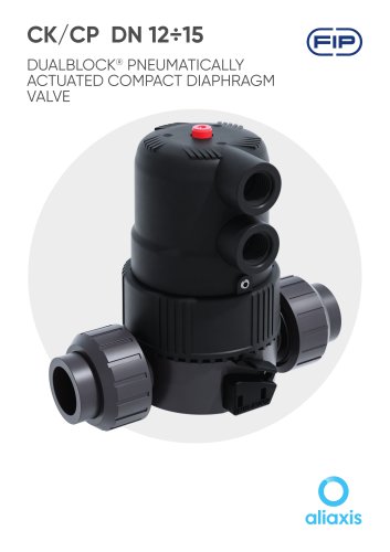 CK/CP DN 12÷15
17 Pages
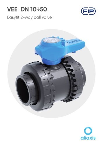 VEE DN 10÷50
15 Pages
Archived catalogs
 PVC-U PRESSURE PIPE
6 Pages
 SXE-SSE 2024
13 Pages
 SXE-SSE DN 10÷50
17 Pages
 VM/RM DN 8÷15
6 Pages
 DK DN
DK DN16 Pages
 VXE EASYFIT DN 65-100
20 Pages
 VEE EASYFIT DN 65-100
16 Pages
 Corporate presentations
12 Pages
 VKD DN 10÷50
16 Pages
 FE DN 40÷200
14 Pages
 Swimming Pool&Spa Solutions
28 Pages
 Chemical Industry Solutions
28 Pages
 Water Treatment solutions
28 Pages
 DK DN 15÷65
16 Pages
 DK/CP DN 15÷20
20 Pages
 SXE-SSE
24 Pages
 VKD Dual Block
6 Pages
 VEE Easyfit Promotional Brochure
16 Pages
 FKOV/FM D355 - D400 ISO-DIN
2 Pages
 VXE Easyfit Promotional Brochur
16 Pages
 PVC-U Manual Valves
246 Pages
 New VKD Ball Valve Dual Block
14 Pages
 C-PVC TemperFIP 100 System
165 Pages
 PVDF System
141 Pages
 Variable Area Flowmeters
14 Pages
 MAGNUM System and Clamp Saddles
12 Pages
 DK DIALOCK 2017
12 Pages


*Prices are pre-tax. They exclude delivery charges and customs duties and do not include additional charges for installation or activation options. Prices are indicative only and may vary by country, with changes to the cost of raw materials and exchange rates.
About DirectIndustry
DirectIndustry is a marketplace that offers B2B players a complete experience, from product sourcing to purchase. DirectIndustry is an entity of VirtualExpo Group.
Are you a buyer?
Are you a supplier?