
- Catalogs
- FIP - Formatura Iniezione Polimeri
- PIPES, FITTINGS AND MANUAL VALVES PVC-C


- Company
- Products
- Catalogs
- News & Trends
- Exhibitions
PIPES, FITTINGS AND MANUAL VALVES PVC-C

PIPES, FITTINGS AND MANUAL VALVES PVC-C
PVC-C, developed by BF Goodrich, is a high-performance resin known for its thermal stability and chemical resistance, suitable for transporting hot corrosive fluids and domestic water systems. It offers high chemical resistance, optimal thermal and mechanical properties, and fire resistance.
TemperFIP100® PVC-C lines adhere to ISO 14001 and ISO 9001 standards, including ANSI B16.5, ASTM D1784, ASTM F437, and EN ISO 15493, ensuring compliance with quality and environmental regulations.
TemperFIP100® PVC-C products are certified by international bodies such as ABS, ACS, Bureau Veritas, DNV-GL, and others, confirming their suitability for water systems on ships and compliance with safety and quality standards.
Solvent welding involves joining PVC-C pipes and fittings using solvent cements. The procedure includes cutting, chamfering, cleaning, and applying solvent cement, with detailed steps and recommendations for effective welding.
Testing up to PN 16 requires a minimum of 24 hours. Solvent cement setting times are valid at approximately 25°C. Insertion, solvent welding, and chamfer lengths are specified for various diameters.
Ensure proper insertion and application of cleaner-primer and solvent cement to avoid joint failures. Use TemperGLUE/Weld-On 724 and Primer P70 for aggressive chemical fluids. Follow safety precautions and perform joining operations within +5°C to +40°C.
Solvent cement issues and incorrect pipe insertion can lead to joint failures and leaks.
Threaded Joints: Use PTFE sealing tape, avoid excessive tightening, and do not use for aggressive fluids or high pressures.
Flanged Joints: Insert backing rings and ensure correct alignment of flanges.
Tables provide theoretical consumption rates for various pipe diameters, indicating the number of joints per kg of solvent cement.
Ensure flange surfaces are not excessively separated. Follow FIP's instructions for solvent welding or welding of fixed flanges or stubs. Tighten bolts in a cross-wise order using a torque wrench to specified values.
Torque values for nuts and bolts are provided for PVC-U or PVC-C flanges with EPDM/FKM/NBR gaskets during pressure tests.
Thermal resistance, low surface roughness, chemical resistance, abrasion resistance, insulating properties, low thermal expansion, easy joining, fire resistance, and mechanical characteristics are highlighted.
Size range: d 16 ÷ d 225 mm. Nominal pressure: SDR 13.6 (PN16) and SDR 21 (PN10) with water at 20°C. Temperature range: 0°C ÷ 100°C.
Details on regression coefficients and pressure variation according to temperature are provided.
Guidelines for the installation of thermoplastic pipe systems, including the use of support clips and distance specifications.
Specifications for various fittings such as elbows, tees, unions, and end caps, including dimensions, pressure ratings, and material codes.
Detailed specifications for various fittings and components used in fluid conveyance systems, including dimensions, pressure ratings, and material compositions.
Installation and coupling procedures are outlined, emphasizing the use of solvent welding and threaded jointing systems.
The fittings comply with international standards like DIN 8063, EN 1092, and ANSI B16.5.
Adhere to specified pressure and temperature ranges for optimal performance.
Comprehensive data on dimensions, pressure ratings, and codes for each component are provided.
Maximum admissible working pressure (PMA) and nominal tightening torque are crucial for ensuring the integrity of the fittings.
The document provides detailed technical specifications and assembly instructions for the VKD DUAL BLOCK® 2-way ball valve, designed for industrial applications.
2-way True Union ball valve with locked carrier and union nuts. Size Range: DN 10 ÷ 50. Nominal Pressure: PN 16 with water at 20°C. Temperature Range: 0°C ÷ 100°C.
Connection system for solvent weld, threaded, and flanged joints. Patented SEAT STOP® system for micro-adjustment of ball seats.
Ensure pipes are aligned to avoid mechanical stress. DUAL BLOCK® system ensures union nut tightening hold.
Handle block kit, wall mounting plate, stem extension, and actuator modules available.
Pressure variation according to temperature for chemically resistant materials.
Detailed steps for disassembling and assembling the valve components.
The document provides detailed technical specifications, installation instructions, and maintenance guidelines for the VKD DUAL BLOCK® 2-way ball valve.
The VKD valve is a True Union ball valve available in sizes DN 65 to 100, with a nominal pressure of PN 16 at 20°C.
The valve includes a patented SEAT STOP® system for micro-adjusting seals, a full bore ball for smooth operation, and a DUAL BLOCK® lock system.
Step-by-step procedures for installing the valve, including aligning pipes and securing union nuts.
The valve allows for micro-adjustments to recover seals using the patented Seat stop system.
Contact the service center when using volatile liquids like Hydrogen Peroxide or Sodium Hypochlorite.
Pressure variation and pressure drop graphs, along with Kv100 flow coefficients for different valve sizes.
The VKD valve features a customizable Labelling System for easy identification.
The document provides detailed technical specifications and operational guidelines for the TKD DUAL BLOCK® 3-way ball valve.
The valve is a 3-way True Union ball valve with a size range of DN 10 to 50 and a nominal pressure of PN 16 at 20°C.
The DUAL BLOCK® system ensures secure union nut tightening, even under severe conditions.
The valve can be installed in any position, including end line or tank.
Contact the service center when using volatile liquids like Hydrogen Peroxide or Sodium Hypochlorite.
Detailed tables with dimensions, pressure variations according to temperature, and Kv100 flow coefficients.
Various accessories are available, including handle block kits, stroke limiters, stem extensions, and modules for pneumatic and electric actuators.
Step-by-step instructions for disassembling and assembling the valve.
The document provides detailed instructions and specifications for the installation, assembly, and maintenance of the VXE DN 10÷50 Easyfit 2-way ball valve.
Ensure pipes are aligned to avoid mechanical stress on threaded joints.
Lubricate rubber seals during assembly, avoiding mineral oils with EPDM rubber.
Size range: DN 10 ÷ 50. Nominal pressure: PN 16 with water at 20°C. Temperature range: 0°C ÷ 100°C.
Customizable Labelling System for identification and service information.
Avoid sudden closing maneuvers and protect the valve from accidental operations.
The document provides detailed technical specifications and installation instructions for the VXE Easyfit True Union ball valve and the SSE Easyfit True Union spring check valve.
Valve Material: PVC-C with elastomer seal elements (EPDM or FKM).
Easyfit System allows for simple installation and maintenance.
Disassembly and Assembly: Detailed steps for disassembling and assembling the valve.
Stem Extension and End Connectors: Options for extending the stem and connecting to pipes.
The VXE and SSE Easyfit valves are designed for ease of use, reliability, and adaptability in various applications.
The document provides detailed specifications for the SSE Easyfit True Union Spring Check Valve.
The Kv100 flow coefficient indicates the flow rate of water at 20°C that results in a 1 bar pressure drop.
The document lists dimensions for various valve sizes (DN 10 to DN 100) and provides codes for EPDM and FKM seals.
Installation instructions emphasize aligning pipes to avoid mechanical stress.
Accessories include long spigot PE100 end connectors, Easyfit handles for union nut tightening, and customisation sets for label printing.
Users are cautioned against using compressed air for testing and advised to avoid sudden closing maneuvers.
Ensure pipes are aligned to avoid stress on joints. Unscrew union nuts and insert them into pipe segments.
Do not use compressed air for testing. Avoid sudden valve closures.
Butterfly valve, DN 40-300, PVC-C material.
Ergonomic handle with locking device.
Pressure variation according to temperature.
Detailed dimensions and codes for various valve sizes and configurations.
Customisable labels for handle identification.
To apply a label on the valve, remove the transparent plug, extract the tag holder, apply the label, and reassemble the components.
The document provides exploded views for DN 40-65, DN 80-200, and DN 250-300, listing components such as position indicators, handles, protection plugs, screws, washers, flanges, tag holders, O-rings, plates, nuts, stems, and disks.
Detailed steps for disassembling and assembling valves for DN 40-200 and DN 250-300 are provided.
Instructions for installing stubs, positioning inserts, and valves are given.
Guidance on tightening stud-bolts to prevent seal damage and handle locking mechanisms for secure operation is provided.
Valves should be supported to avoid sudden closures and accidental operations.
The valve is designed for abrasive or dirty fluids, offering features like a lockable handwheel, modularity, and a CDSA system for reduced mechanical stress.
Details include construction, size range, pressure, temperature range, coupling standards, and materials.
Graphs and tables provide information on pressure variations, pressure drop, and flow coefficients for different valve sizes.
Dimensions for DKDC DIALOCK® diaphragm valves with male ends for solvent welding are listed.
The document provides detailed specifications and instructions for various models of DIALOCK® diaphragm valves.
Each valve series is described with parameters such as diameter (d), nominal diameter (DN), nominal pressure (PN), and dimensions.
- DKDC and DKLDC: Valves with stroke limiters and male ends for solvent welding.
- DKUIC and DKLUIC: Valves with female union ends for solvent welding.
- DKUFC: Valves with BSP threaded female union ends.
- DKUAC: Valves with female union ends for solvent welding, ASTM series.
- DKOC and DKOAC: Valves with flanged monolithic bodies, drilled according to specific standards.
Step-by-step instructions for disassembling and assembling the valves are provided.
The valves feature a customisation plate for identification and a DIALOCK® handwheel locking system.
The VM series diaphragm valve is highlighted for its optimized fluid dynamics, ergonomic handwheel, and suitability for abrasive or dirty fluids.
The document includes pressure variation according to temperature and a pressure drop graph.
The document provides detailed specifications for various types of diaphragm valves and sediment strainers.
1. VMDC and VMOC Series: These valves are available with male ends or flanged bodies.
2. CM Series: Compact diaphragm valves designed for confined spaces.
Step-by-step procedures for assembling and disassembling the valves are outlined.
1. RV Series: These strainers limit the passage of solid particles.
2. Installation and Maintenance: The strainers can be installed in any position.
Graphs and tables for pressure variation according to temperature and Kv100 flow coefficients are provided.
Mineral oils are not recommended for lubricating rubber seals.
- Unscrew the union nuts and slide them onto the pipe.
- Heat weld the end connectors onto the pipe segments.
- Position the sediment strainer between the end connectors.
- Tighten the union nuts.
- Sediment strainers with a transparent body allow light passage, promoting algae and microorganism growth.
- These strainers are not protected against solar rays, which accelerates material aging and reduces working life.
- Protect strainers near pumps from vibrations.
- Regularly check the cleanliness of the strainer elements.
- Maintain a straight pipe section of length equal to 5 times the nominal diameter before and after the valve.
- ABS: Acrylonitrile butadiene styrene
- DN: Nominal internal diameter of the pipe in mm
- EPDM: Ethylene-Propylene-Diene-Monomer
- PN: Nominal pressure in bar
- PVC-U: Unplasticized polyvinylchloride
- And others as listed in the document.
FIP Formatura Iniezione Polimeri
Loc. Pian di Parata, 16015 Casella Genova Italy
Tel. +39 0109621.1 - Fax +39 010 9621.209
Email: [email protected]
Website: www.fipnet.com
- UNI EN ISO 9001: Quality Management
- UNI EN ISO 14001: Environmental Management
Catalog excerpts

Technical catalogue Manual valves, pipe and fittings in PVC-C Pressure piping fluids conveying
Open the catalog to page 1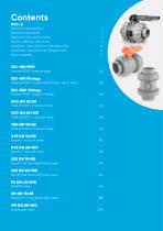
Contents PVC-C General characteristics Reference standards Approvals and quality marks Solvent welding instructions Installation instructions for threaded joints Installation instructions for flanged joints Main properties ISO-UNI PIPE ISO-UNI Fittings TemperFIP100® solvent weld fittings, metric series ISO-BSP Fittings DUAL BLOCK® 2-way ball valve DUAL BLOCK® 2-way ball valve DUAL BLOCK® 3-way ball valve Easyfit 2-way ball valve Easyfit 2-way ball valve Easyfit True Union ball check valve Easyfit True Union ball check valve Butterfly valve DIALOCK® 2-way diaphragm valve Diaphragm valve
Open the catalog to page 3
Compact diaphragm valve Sediment strainer
Open the catalog to page 4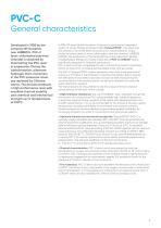
General characteristics Developed in 1958 by the company BF Goodrich, now LUBRIZOL, PVC-C (post-chlorinated polyvinyl chloride) is obtained by chlorinating the PVC resin in suspension. During the transformation, alternate hydrogen atom monomers in the PVC molecular chain are replaced by Chlorine atoms. The process produces a high performance resin with excellent thermal stability and chemical and mechanical strength up to temperatures of 100°C. In 1986, FIP were the first European Company to produce an integrated system of valves, fittings and pipes called TemperFIP100®. The result was the creation...
Open the catalog to page 5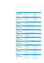
Density Test method Unit of measurement Value Modulus of elasticity Test method Unit of measurement ISO 178 ASTM D790 2 MPa = N/mm MPa = N/mm2 Valves/fittings: 2800 Valves/fittings: 2992 Value Pipes: 2420 Pipes: 2689 IZOD notched impact strength at 23°C Test method ASTM D256 Unit of measurement ftlbs/in Value Valves/fittings: 1.8 - Pipes: 1.6 Ultimate elongation Test method ISO 527-1, ISO 527-2 Unit of measurement % Value Valves/fittings: 16 - Pipes: 5 Rockwell hardness Test method ASTM D 785 Unit of measurement R Value Valves/fittings: 120 - Pipes: 116 Tensile strength Test method ISO 527-1,...
Open the catalog to page 6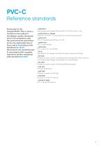
Reference standards Production of the TemperFIP100® PVC-C lines is carried out according to the highest quality standards and in full compliance with the environmental restrictions set by the applicable laws in force and in accordance with standard ISO 14001. All products are manufactured in accordance with a quality assurance system complying with standard ISO 9001. l ANSI B16.5 Pipe flanges and flanged fittings-NPS 1/2 to NPS 24 mm / inch l ASTM D1784 cl. 23548B Rigid PVC and PVC-C compounds (for industrial applications). l ASTM F437 PVC-C threaded pipe fittings, sch. 80. l ASTM F439 PVC-C...
Open the catalog to page 7
l DIN 16962 PVC-C fittings for butt-welding or socket fusion, dimensions. l DIN 16963 Pipe connections and pipe components for pressurised fluids in HDPE. l EN 558-1 Industrial valves - face-to-face and centre-to-face dimensions of metal valves for use in flanged pipe systems - Part 1: PN designated valves. EN 1092-1 Flanges and their joints - Circular flanges for pipes, valves and accessories - Part 1: Steel flanges, PN designated. l EN ISO 15493 Specifications for components and the system (Pipes, Fittings and Valves) in PVC-C for industrial applications. l ISO 228-1 PVC-C fittings with threaded...
Open the catalog to page 8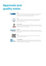
Approvals and quality marks l ABS FIP PVC-U valves have been recongnised as suitable for conveying, treating domestic and air conditioning waters on board ships and other units classified by the American Bureau of Shipping (ABS) l ACS FIP PVC-U ball valves are certified as suitable for coming into contact with water intended for human consumption according to the Attestation de conformité sanitaire (ACS) l Bureau Veritas FIP PVC-U valves have been recognised as suitable for conveying, treating domestic and air conditioning waters on board ships and other units classified by the Bureau Veritas...
Open the catalog to page 9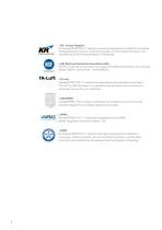
l KR - Korean Register FIP TemperFIP100 PVC-C system has been recognised as suitable for conveying, treating domestic and air conditioning waters on board ships and other units classified by the KR (Korean Register of Shipping) NSF (National Sanitation Foundation USA) FIP PVC-C ball valves are listed according to the NSF/ANSI Standard 61 -Drinking Water System Components - Health Effects. l TA-Luft TemperFIP100® PVC-C valves have been tested and certified according to “TA-Luft” by MPA Stuttgart in compliance with the Technical Instruction on Air Quality Control TA-Luft/ VDI 2440. l UKR SEPRO...
Open the catalog to page 10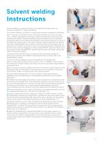
Solvent welding Instructions Solvent welding, or cement jointing, is the longitudinal joining system for connecting rigid PVC-C pipes and fittings. The “solvent welding” is carried out using solvent cements obtained by dissolving PVC-C polymer in a solvent mixture. This solvent liquefies the walls of the pipe and/ or fitting, allowing the constituent material to chemically combine and be subsequently welded. Chemical welding allows permanent joints be achieved possessing chemical and mechanical strength characteristics identical to those of the pipes and fittings joined. The solvent cements must...
Open the catalog to page 11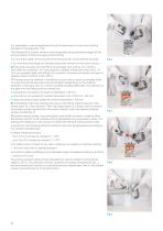
It is advisable to use an applicator/brush of dimensions not less than half the diameter of the pipe (fig. 7-8). The TemperGLUE solvent cement must be applied along the entire length of the joining surface of both the pipe and the fitting: l for the entire depth of the socket of the fitting as far as the internal shoulder for the entire joint length of the pipe previously marked on the outer surface 6) Fully insert the pipe into the fitting immediately and without any rotation. Only after this operation will it be possible to slightly rotate both ends (max. 1/4 of a turn between pipe and fitting)....
Open the catalog to page 12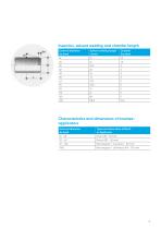
LUNGHEZZA DI INSERZIONE INCOLLAGGIO E SMUSSO DEL TUBO Insertion, solvent welding and chamfer length External diameter Solvent welding length incollaggio Chamfer Diametro esterno Lunghezza di de (mm) L (mm) Sm (mm) de (mm) L (mm) 16 Serie Metrica 20 25 Type and dimensions of Brush 163,5 168 or Applicator 75 - 160 Rectangular / round (45 - 50 mm) CARATTERISTICHE E DIMENSIONI DEI PENNELLI - APPLICATORI >160 Tipologia e dimensioni del Pen o Applica Rotondo (8 - 10
Open the catalog to page 13All FIP - Formatura Iniezione Polimeri catalogs and technical brochures
 CK/CP DN 12÷15
17 Pages
 CK/CP DN 12÷15
17 Pages
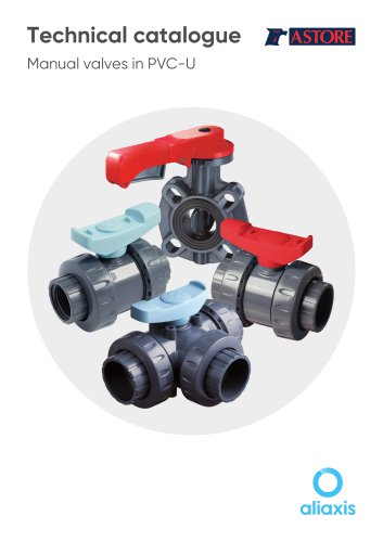 Manual valves in PVC-U
81 Pages
 PIPE ISO-UNI
10 Pages
 FLS
FLS228 Pages
 PP-H
PP-H254 Pages
 PVC-U
PVC-U460 Pages
 PVC-U Fittings
114 Pages
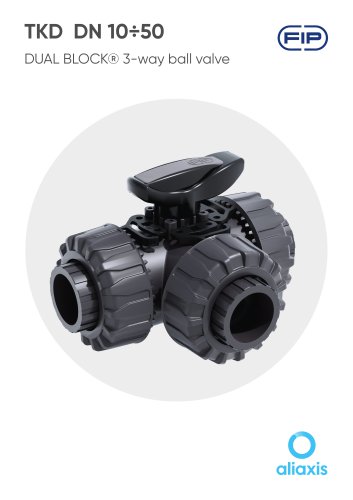 TKD DN 10÷50
19 Pages
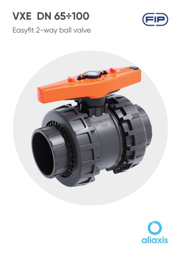 VXE DN 65÷100
13 Pages
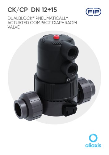 CK/CP DN 12÷15
17 Pages
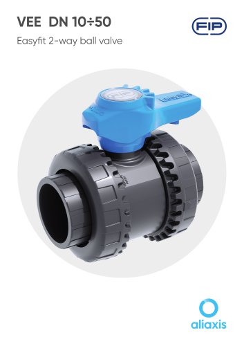 VEE DN 10÷50
15 Pages
Archived catalogs
 PVC-U PRESSURE PIPE
6 Pages
 SXE-SSE 2024
13 Pages
 SXE-SSE DN 10÷50
17 Pages
 VM/RM DN 8÷15
6 Pages
 DK DN
DK DN16 Pages
 VXE EASYFIT DN 65-100
20 Pages
 VEE EASYFIT DN 65-100
16 Pages
 Corporate presentations
12 Pages
 VKD DN 10÷50
16 Pages
 FE DN 40÷200
14 Pages
 Swimming Pool&Spa Solutions
28 Pages
 Chemical Industry Solutions
28 Pages
 Water Treatment solutions
28 Pages
 DK DN 15÷65
16 Pages
 DK/CP DN 15÷20
20 Pages
 SXE-SSE
24 Pages
 VKD Dual Block
6 Pages
 VEE Easyfit Promotional Brochure
16 Pages
 FKOV/FM D355 - D400 ISO-DIN
2 Pages
 VXE Easyfit Promotional Brochur
16 Pages
 PVC-U Manual Valves
246 Pages
 New VKD Ball Valve Dual Block
14 Pages
 PP-H (100) System
198 Pages
 C-PVC TemperFIP 100 System
165 Pages
 PVDF System
141 Pages
 Variable Area Flowmeters
14 Pages
 MAGNUM System and Clamp Saddles
12 Pages
 DK DIALOCK 2017
12 Pages

- VirtualExpo Group
- Our Partners
- Recruitment
- Testimonials