- Catalogs
- FIP - Formatura Iniezione Polimeri
- DK DN 15÷65
- Company
- Products
- Catalogs
- News & Trends
- Exhibitions
DK DN 15÷65
1 /16Pages

DK DN 15÷65
1 /16Pages
Catalog excerpts

DIALOCK® 2-way diaphragm valve
Open the catalog to page 1
DK DN 15÷65 DIALOCK® 2-WAY DIAPHRAGM VALVE The new DK DIALOCK® diaphragm • Connection system for solvent weld, threaded and flanged joints valve is particularly • Optimised fluid dynamic design: maximum output flow rate thanks to the suitable for shutting optimised efficiency of the fluid dynamics that characterise the new internal geometry of the body off and regulating • Internal components in metal, totally isolated from the fluid and external enabrasive or dirty vironment fluids. The new • Modularity of the range: only 2 handwheel and 4 diaphragm and bonnet sizes for 7 different valve sizes...
Open the catalog to page 2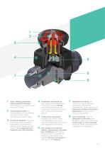
High visibility graduated optical position indicator protected by a transparent cap with seal O-Ring Customisation plate: the customisation lets you identify the valve on the system according to specific needs DIALOCK® SYSTEM: innovative handwheel with a patented immediate and ergonomic operating locking device that allows it to be adjusted and locked in over 300 positions Handwheel and bonnet in high mechanical strength and chemically resistant PP-GR, providing full protection by isolating all internal metal parts from contact with external agents Floating pin connection between the control...
Open the catalog to page 3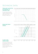
TECHNICAL DATA PRESSURE VARIATION ACCORDING TO TEMPERATURE For water and harmless fluids to which the material is classified as CHEMICALLY RESISTANT. In other cases, a reduction of the nominal pressure PN is required (25 years with safety factor). Pressure drop PRESSURE DROP GRAPH KV100 FLOW COEFFICIENT The Kv100 flow coefficient is the Q flow of litres per minute of water at a temperature of 20°C that will generate ∆p= 1 bar pressure drop at a certain valve position. The Kv100 values shown in the table are calculated with the valve completely open.
Open the catalog to page 4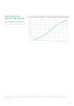
RELATIVE FLOW COEFFICIENT GRAPH 100 90 Relative flow coefficient The relative flow coefficient refers to the variation in the flow rate as a function of the valve opening stroke. The information in this leaflet is provided in good faith. No liability will be accepted concerning technical data that is not directly covered by recognised international standards. FIP reserves the right to carry out any modification. Products must be installed and maintained by qualified personnel.
Open the catalog to page 5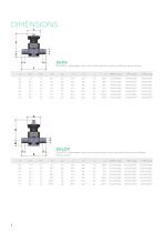
DIALOCK® diaphragm valve with male ends for solvent welding, metric series EPDM Code DIALOCK® diaphragm valve with stroke limiter and male ends for solvent welding, metric series d EPDM Code
Open the catalog to page 6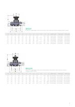
DIALOCK® diaphragm valve with female union ends for solvent welding, metric series EPDM Code PTFE Code DIALOCK® diaphragm valve with stroke limiter and female union ends for solvent welding, metric series d EPDM Code PTFE Code
Open the catalog to page 7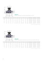
DIALOCK® diaphragm valve with BSP threaded female union ends EPDM Code PTFE Code DKLUFV version available on request DIALOCK® diaphragm valve with female union ends for solvent welding, ASTM series EPDM Code PTFE Code DKLUAV version available on request
Open the catalog to page 8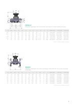
DIALOCK® diaphragm valve with female union ends for solvent welding, BS series EPDM Code PTFE Code DKLULV version available on request DIALOCK® diaphragm valve with fixed flanges, drilled PN10/16. Face to face according to EN 558-1 d EPDM Code PTFE Code DKLOV version available on request
Open the catalog to page 9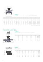
DIALOCK® diaphragm valve with fixed flanges, drilled ANSI B16.5 cl. 150 #FF EPDM Code PTFE Code DKLOAV version available on request ACCESSORIES Q/BBE-L Long spigot PE100 end connectors for electrofusion or butt welding Wall Mounting plate
Open the catalog to page 10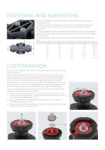
FASTENING AND SUPPORTING All valves, whether manual or actuated, must be adequately supported in many applications. The DK valve series is therefore provided with an integrated bracket that permits direct anchoring of the valve body without the need of other components. For wall installation, dedicated PMDK mounting plates which are available as accessories can be used. These plates should be fastened to the valve before wall installation. The PMDK plate also allows the DK valve to be aligned with FIP ZIKM pipe clips. d CUSTOMISATION The DIALOCK® DK DN 15÷65 valve can be customised using a customisation...
Open the catalog to page 11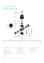
COMPONENTS EXPLODED VIEW DN 15÷50 7 Diaphragm seal 2 Customisation plate (EPDM, FPM, PTFE - 1)* (PVC - 1) 8 Valve body (PVC-U - 1)* 3 O-Ring (EPDM - 1) 9 Socket seal O-ring 4 Operating mechanism (PP-GR / PVDF - 1) 5 Threaded stem - Indicator (Stainless steel - 1) * Spare parts ** Accessories The material of the component and the quantity supplied are indicated between brackets 12 Washer (Stainless steel - 4) 13 Bolt (Stainless steel - 4) 14 Protection plug (PE - 4) 15 Distance plate (PP-GR - 1)** 16 Screw (Stainless steel - 2)**
Open the catalog to page 12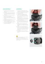
1) Isolate the valve from the line (release the pressure and empty the pipeline). 2) If necessary, release the handwheel by pressing downwards (fig.5) and rotating anticlockwise to fully open the valve. 3) Unscrew the union nuts (11) and extract the valve sideways. 4) Remove the protection plugs (14) and bolts (13) with the relative washers (12). 5) Separate the valve body (8) from the internal components (4). 6) Rotate the handwheel clockwise to free the threaded stem (5), compressor (6) and diaphragm (7) 7) Unscrew the diaphragm (7) and remove the shutter (6). 1) Insert the compressor (6) on...
Open the catalog to page 13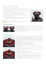
INSTALLATION Before proceeding with installation. please follow these instructions carefully: (these instructions refer to union end versions). The valve can be installed in any position and in any direction. 1) Check that the pipes to be connected to the valve are aligned in order to avoid mechanical stress on the threaded joints. 2) Unscrew the union nuts (11) and insert them on the pipe segments. 3) Solvent weld or screw the end connectors (10) onto the pipe ends. 4) Position the valve body between the end connectors, making sure that the socket seal O-rings (9) do not exit their seats. 5)...
Open the catalog to page 14
UTILITIES & INDUSTRY FIP - Formatura Iniezione Polimeri Loc. Pian di Parata, 16015 Casella Genova Italy
Open the catalog to page 16All FIP - Formatura Iniezione Polimeri catalogs and technical brochures
 SXE-SSE 2024
13 Pages
 PVC-U PRESSURE PIPE
6 Pages
 FITTINGS PVC-U
134 Pages
 FS - FC
16 Pages
 S1 - S2
12 Pages
 Water Treatment solutions
28 Pages
 Chemical Industry Solutions
28 Pages
 Swimming Pool&Spa Solutions
28 Pages
 PVC-U Fittings
114 Pages
 FE DN 40÷200
14 Pages
 VKD DN 10÷50
16 Pages
 Corporate presentations
12 Pages
 TKD Dual Block
14 Pages
 VEE EASYFIT DN 10-50
16 Pages
 VEE EASYFIT DN 65-100
16 Pages
 VXE EASYFIT DN 10-50
16 Pages
 VXE EASYFIT DN 65-100
20 Pages
 DK DN
DK DN16 Pages
 DK CP
DK CP45 Pages
 VM/RM DN 8÷15
6 Pages
 SXE-SSE DN 10÷50
17 Pages
 DK/CP DN 15÷20
20 Pages


Archived catalogs
 SXE-SSE
24 Pages
 VKD Dual Block
6 Pages
 VEE Easyfit Promotional Brochure
16 Pages
 FKOV/FM D355 - D400 ISO-DIN
2 Pages
 VXE Easyfit Promotional Brochur
16 Pages
 PVC-U Manual Valves
246 Pages
 New VKD Ball Valve Dual Block
14 Pages
 PP-H (100) System
198 Pages
 C-PVC TemperFIP 100 System
165 Pages
 PVDF System
141 Pages
 Variable Area Flowmeters
14 Pages
 MAGNUM System and Clamp Saddles
12 Pages
 DK DIALOCK 2017
12 Pages


- Liebherr piping
- Liebherr fitting
- Liebherr manual valve
- Liebherr control valve
- Liebherr flow meter
- Liebherr stainless steel valve
- Liebherr hydraulic fitting
- Liebherr water valve
- Liebherr screw-in fitting
- Liebherr ball valve
- Volume flow monitor
- Liebherr pneumatic valve
- Liquid flow monitor
- Liebherr solenoid valve
- Liebherr threaded valve
- Liebherr metal fitting
- Liebherr regulating valve
- Liebherr liquid filter
- Liebherr flange valve