- Catalogs
- Finn Test Electronics
- Smart FINN Bright
Smart FINN Bright
1 /17Pages
Smart FINN Bright
1 /17Pages
Catalog excerpts

Smart FINN® and Smart FINN® Bright Specification Manual Smart FINN® Smart FINN® Bright Information in this document is provided in connection with the Smart FINN® products. FINN Test Electronics (FTE) shall not be liable for errors or damages sustained in connection with the delivery, use or performance of this document and the information contained herein. Provision of this document does not in any way constitute recommendation of product fitness for a specific purpose. In future publications, FTE may make changes to specifications and product descriptions at any time, without notice. Contact FTE or your distributor to obtain the latest specifications prior to placing your product order. U. S. Patent Nos: 6,490,037; 7,023,554; 7,227,639 and 7,265,822. Additional patents pendin
Open the catalog to page 1
1. Part Numbers and Descriptions Smart FINN Part numbers – LEDs intensity up to 100mcd Part Number TC11SF-R TC11SF-V TC11SF-C Description Right Angle Smart FINN® Vertical Smart FINN® 3-Pin Header Connector Smart FINN® (no probes) Smart FINN Bright Part numbers – LEDs intensity greater than 100mcd Part Number TC16SFBright-R TC16SFBright-V Description Right Angle Smart FINN® Bright Vertical Smart FINN® Bright 2. Principal of Operation The Smart FINN® boasts an all-in-one sensor – four sensors combined into one. Each sensor is designed to detect a certain range of color – blue, red, green or clear....
Open the catalog to page 3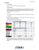
6. Properties 6.1. Dimensions 0.486 inch x 0.485 inch x 0.176 inch (not including spring probes) 6.2. Power Source Unlike the original FINN®, the Smart FINN® requires a minimal power voltage source, which may vary from 2.7 volts to 5.5 volts, current is typically 8mA@5V. Power is marked with a + (plus) sign on the PCB and red heat-shrink on the probe. Ground is marked with a – (minus) sign on the PCB and black heat-shrink on the probe. 6.3. Sensor Four sensors combined into one specially designed to detect color: Blue, Red, Green and Clear. 6.4. Controller Because this system is microcontroller...
Open the catalog to page 4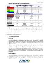
Rev D - 012516 6.6. Smart FINN Bright Table of Typical Measurements Color Red Amber Yellow Green Blue Infrared Ultraviolet Fluorescent White(red dominant) White(blue dominant) Saturation *These values are for typical environments (25 degrees Celsius). For additional detail, please refer to the technical discussions later in this document. Please note the voltage output is dependent on the color. The highest voltage is output for red and declines as the wavelength declines. 7. Understanding Measurements 7.1. Voltage and Brightness Smart FINN This sensor is designed to accommodate a wide range...
Open the catalog to page 5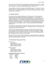
Rev D - 012516 The lower range is for LED’s with lower output intensity, typically less than 2,000mcd. The lower range output is from 0 to Vdd/2, if using Vdd@5Vdc then a 2,000mcd LED gives an output of 2.5V. The output is not linear so a 1,000mcd LED would give 2.0Volts DC out. The upper range is for LED’s with roughly 2,000-20,000mcd outputs. The output of the range starts at Vdd/2. The increase in voltage per mcd is 1/8 the increase on the lower scale. So, for a 3,000mcd LED the first 2,000mcd accounts for 2.5volts in the output and the next 1,000mcd accounts for only 0.75Volts DC. 7.2. Frequency...
Open the catalog to page 6
Rev D - 012516 *If the sensor is powered up before the LED the first reading cycle may have samples from the unlit time period and thus a second sampling period is needed. If using Test Flow A, then the wait can be reduced to half the worst case. Also wait times can be reduced if the voltage is measured before the frequency. 8. Sources of Error 8.1. Wiring Special care should be paid to the wiring instructions in section 9.1. Improper wiring will result in over-heating and damage to the part. If miss-wiring has occurred, immediate replacement of the damaged part is recommended. 8.2. Outside light...
Open the catalog to page 7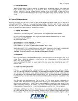
Rev D - 012516 8.7. Socket Set Height When multiple Smart FINNs are used in the same fixture or duplicate fixtures, then socket set height of each Smart FINN must be the identical. If the socket set heights are varying from location to location, then the voltage(intensity) reading of the Smart FINNs will also vary since some of the Smart FINN will be closer to the LED making the voltage reading stronger, and vice versa. 9. Fixture Considerations Drawings in section 15, 16, and 17 show the TC11SF-R (Right Angle Smart FINN) and the TC11SF-V (Vertical Smart FINN). There are 2 other part numbers...
Open the catalog to page 8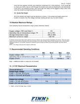
Rev D - 012516 Once the face appears smooth use cardboard (unpainted) for a final polishing. If you would like to check your finish, view an LED through the conduit and verify the brightness is not diminished. If the end is not polished enough, then some light will reflect off the jagged surface rather than enter the conduit and brightness will be reduced. 9.4. Socket Set Height All of the sockets set height must be identical in a fixture. If the socket set height varies from location to location then the voltage (intensity) reading will also vary for each location. 10.Absolute Maximum Ratings...
Open the catalog to page 9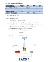
13. 3-V DC Electrical Characteristics Characteristics(1) Output high voltage ILoad = –0.6 mA, all I/O pins ILoad = –4.0 mA, all I/O pins Output low voltage ILoad = 0.5 mA, all I/O pins ILoad = 6.0 mA, all I/O pins 14.Other Application Notes 14.1. Low Pass Filter for DC Measurements Some meters will not average for DC voltage measurement. If your meter does not average you can add a simple low pass filter (R=10k, C=0.1uf) to the output for DC measurements. You must wait at least 5msec after the sensor has acquired a reading to get a stable voltage on the capacitor of the low pass filter. Also,...
Open the catalog to page 10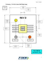
15.Drawing – TC11SF-R, Smart FINN® Right Angle 0.4812 (12.25)
Open the catalog to page 11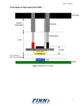
16.Set Height for Right Angle Smart FINN®
Open the catalog to page 12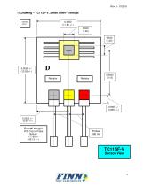
17.Drawing – TC11SF-V, Smart FINN® Vertical 0.4650 (11.81 +/-) Overall Length: PCB Top to Probe Bottom 1.7765 +/(45.13 +/-)
Open the catalog to page 13
18.Technical Support Our product engineers are available to assist you with choosing the correct FINN TM product to fit your specific needs as well as to answer any technical questions you may have regarding installation and/or implementation. Please contact us at: Email: [email protected] Phone: 224-662-0383 19.Revision History and Control 19.1. Rev D 3.0 – January 2016 No Rev Change to part - Logo and layout changes to manual only. Added information on new part: Smart FINN Bright. 19.2. Rev D 3.0 – December 2010 The Smart FINN TC11SF-x incorporates new part changes which have some minor...
Open the catalog to page 14All Finn Test Electronics catalogs and technical brochures
 Mega FINN™
13 Pages
 MEGA FINN™ MODULE
24 Pages
 FINN®
FINN®11 Pages
 FINNtrometer™
2 Pages