- Catalogs
- Finn Test Electronics
- MEGA FINN™ MODULE
MEGA FINN™ MODULE
1 /24Pages

MEGA FINN™ MODULE
1 /24Pages
Catalog excerpts

Mega FINNTM MODULE Specification Manual Information in this document is provided in connection with the Mega FINNTM Module product. FINN Test Electronics (FTE) shall not be liable for errors or damages sustained in connection with the delivery, use or performance of this document and the information contained herein. Provision of this document does not in any way constitute recommendation of product fitness for a specific purpose. In future publications, FTE may make changes to specifications and product descriptions at any time, without notice. Contact FTE or your distributor to obtain the latest specifications prior to placing your product order. U. S. Patent Nos: 6,490,037; 7,023,554; 7,227,639; 7,265,822 and 10094877. Additional patents pending.
Open the catalog to page 1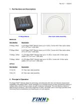
1. Part Numbers and Descriptions Fiber Optic Cable Assembly MODULES Part Number 4 LED Mega FINNTM Module (tests up to 4 LEDs). Comes with 4 fiber optics cables (18” or 24”) and 1 USB cable. 8 LED Mega FINNTM Module (tests up to 8 LEDs). Comes with 8 fiber optics cables (18” or 24”) and 1 USB cable. 12 LED Mega FINNTM Module (tests up to 12 LEDs). Comes with 12 fiber optics cables (18” or 24”) and 1 USB cable. 16 LED Mega FINNTM Module (tests up to 16 LEDs). Comes with 16 fiber optics cables (18” or 24”) and 1 USB cable. OPTICS Part Number 18” Fiber optic cable assembly 24” Fiber optic cable assembly...
Open the catalog to page 3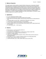
3. Method of Operation The module houses a custom assembly, including multicolor sensors and a microprocessor. Separate optical cables that are comprised of a press fit plug connect to numbered ports on the module and a metal shrouded tip on the opposite end which is placed in front or on top of the LED to be tested. When a command for a specific numbered cable is sent to the module, the module will measure the color and/or intensity of the requested cable and send back the measurement via the chosen interface. Readings may be provided in either frequency (Hz) or in voltage (V) for the LED color...
Open the catalog to page 4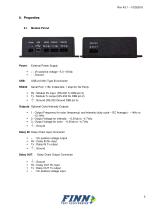
Module Pinout External Power Supply + : Vin positive voltage ~5.0 -16Vdc - : Ground USB 2.0 Mini Type B connector Serial Port: 115k, 8 data bits, 1 stop bit, No Parity Rx : Module Rx input (RS-232 Tx DB9 pin 3) Tx : Module Tx output (RS-232 Rx DB9 pin 2) Outputs: Optional Color/Intensity Outputs ▪ ▪ ▪ 1 : Output Frequency for color (frequency) and intensity (duty cycle – DC Average) - ~1kHz to ~13.1kHz 2 : Output Voltage for intensity - ~0.2Vdc to ~4.7Vdc 3 : Output Voltage for color - ~0.2Vdc to ~4.7Vdc Daisy IN: Daisy Chain Input Connector ▪ ▪ ▪ + : Vin positive voltage output Rx : Daisy IN...
Open the catalog to page 5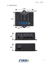
Module Dimensions
Open the catalog to page 6
Fiber Optics Dimensions 18” Fiber optic cable assembly 24” Fiber optic cable assembly Plastic Fiber Optics. 1.00mm optical fiber core and ~1.3mm OD with jacket. Minimum bending radius is 25mm. Metal tip custom connector that press fit in to the sensor hole on the Module body. Metal tip custom connector that is placed in front or over of the LED under test. Power Source The Mega FINNTM Module requires ~5.0-16.0 Volts DC or powered directly from USB cable. Current is typically ~27 mA for 4 channels version. Current is typically ~54 mA for 8 channels version. Current is typically ~81 mA for 12 channels...
Open the catalog to page 7
Light- to- frequency converter sensors are comprised of an 8 x 8 array of photodiodes, 16 photodiodes each of blue, green and red filters and 16 photo-diodes of clear, with no filter. The micro controller, in combination with the precision MHz high frequency clock source, allows for extremely fast and accurate sampling of the light source under test. Fiber Optic cables The Mega FINNTM Module has two fiber optic options available – an 18” cable assembly and a 24” cable assembly. The smaller press fit plug end of the cable assembly fits into corresponding labeled socket in the top of the module...
Open the catalog to page 8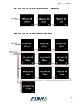
6.8.1. Daisy Chain with USB cable and no power supply - 3 Modules max 6.8.2. Daisy Chain with USB cable and External Power Supply
Open the catalog to page 9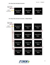
Rev A3.1 – 10252018 6.8.1.Daisy Chain with Serial Connection 6.8.1.Daisy Chain with Serial Connection – Multiple Modules
Open the catalog to page 10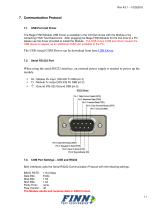
The Mega FINN Module USB Driver is available in the CD that comes with the Module or by contacting FINN Test Electronics. After plugging the Mega FINN Module for the first time to a PC, please use the driver provided to install the Module. The USB virtual COM port driver causes the USB device to appear as an additional COM port available to the PC. The USB virtual COM Driver can be download from here USB Driver . 7.2. When using the serial RS232 interface, an external power supply is needed to power up the module. ▪ ▪ ▪ Rx : Module Rx input (RS-232 Tx DB9 pin 3) Tx : Module Tx output (RS-232...
Open the catalog to page 11
Module Commands Pxxx Yxxx S C E TRIG Read Color (Frequency HZ) and Intensity (V) Read Dominant Wavelength (nm) And Intensity (%) Read Chain Size ( total number of fibers connected) Turn On Continuous Sampling Echo last Color (Hz) and Intensify(V) readings Trigger reading request (broadcast) to all of the fibers connected to the entire chain. This command is used remove a fiber optic channel from the TRIG command listed above This command is used add a fiber optic channel to the TRIG command listed above. Every command sent to Module must end with a Line Feed . A Carriage Return can also be sent...
Open the catalog to page 12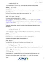
Rev A3.1 – 10252018 7.4.2.Echo Command – E This command is used to re-send the color and intensity of last fiber optic channel requested. Command: E Example: E The Module will re-send the last requested measurement of color and intensity. The answer is 16 bytes string including a The answer to this command is always a 16 bytes string followed by . Pxxx ; yyyyy ; z.zzz xxx is the fiber optics channel requested from 001 to 254. yyyyy is the frequency (color) reading for the fiber requested in Hz from 00998 to 13100. See Output Frequency Graph Section. z.zzz is the voltage (intensity) reading for...
Open the catalog to page 13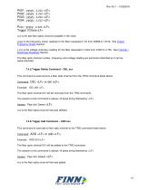
P001 ; yyyyy ; z.zzz P002 ; yyyyy ; z.zzz P003 ; yyyyy ; z.zzz P004 ; yyyyy ; z.zzz …. Pxxx ; yyyyy ; z.zzz Trigger if Done xxx is the last fiber optics channel available in the chain. yyyyy is the frequency (color) reading for the fiber requested in Hz from 00998 to 13100. See Output Frequency Graph Section. z.zzz is the voltage (intensity) reading for the fiber requested in Volts from 0.200 to 4.750. See Intensity / Brightness Readings Section. The fiber optic channel number, frequency and voltage reading are semicolon delimited so it can be easily decoded. 7.4.5.Trigger Delete Command – DEL...
Open the catalog to page 14All Finn Test Electronics catalogs and technical brochures
 Mega FINN™
13 Pages
 FINN®
FINN®11 Pages
 Smart FINN Bright
17 Pages
 FINNtrometer™
2 Pages