

FINN®

FINN®
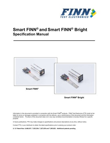
The FINN® sensor is engineered to detect LED colors using a photosensitive semiconductor paired with an optical filter. It selectively allows light of specific wavelengths to pass, generating a measurable current. The sensor's compact design, lack of power requirement, and minimal wiring facilitate easy integration into test fixtures.
The document enumerates various part numbers for FINN® configurations, including Red, Green, Blue, Clear, and Infrared sensors, available in both Right Angle and Vertical orientations.
A table outlines nominal wavelengths for different LED colors and the corresponding peak sensitivity wavelengths of the FINN® sensors. It notes the challenge in distinguishing between green and yellow LEDs, recommending a green sensor for improved accuracy.
Typical voltage readings for various LED colors are provided, with advice on adjusting sensor placement and LED intensity to prevent saturation. Strategies for managing bright LEDs and ambient light interference are also included.
Guidelines for sensor mounting using industry-standard sockets are provided, along with recommendations to minimize ambient light interference. Applications for edge-mounted and SMT LEDs are described, with specific setup instructions.
Instructions for configuring FINN® sensors in HP programming environments are detailed, including board file setup and pin location calculations for both vertical and right-angle setups.
This document outlines technical details and specifications for FINN® sensors, covering both vertical and right-angle styles, sensor dimensions, probe details, and technical support.
Sensor dimensions are uniform across all styles and color options. FINN® sensors use QA Technologies 025-26 series probes.
Recommended companies and part numbers for obtaining appropriate sockets include:
- QA Technologies: 100-SDN250W
- Everett Charles Technologies: SPR 25W2
- INGUN: KS 925 47 G
- IDI: R100WW
Product engineers are available for product selection and technical inquiries related to installation and implementation. Contact information:
- Email: [email protected]
- Phone: 224-662-0383
- Rev A - January 2016: No part changes; updates to logo and manual layout.
- Rev A - January 1999: Initial release.
Catalog excerpts

FINN® Specification Manual Information in this document is provided in connection with the FINN® product. FINN Test Electronics (FTE) shall not be liable for errors or damages sustained in connection with the delivery, use or performance of this document and the information contained herein. Provision of this document does not in any way constitute recommendation of product fitness for a specific purpose. In future publications, FTE may make changes to specifications and product descriptions at any time, without notice. Contact FTE or your distributor to obtain the latest specifications prior to placing your product order. U. S. Patent Nos: 6,490,037; 7,023,554; 7,227,639 and 7,265,822. Additional patents pending.
Open the catalog to page 1
The FINN sensor is a low cost solution for detecting the color of light emitting diodes (LEDs). It is a combination of a photosensitive semiconductor and an optical filter. The filter allows light of a target wavelength (color) to pass through and blocks light of wavelengths outside the target color wavelength. The sensor produces current when excited by the target wavelength of light. The current creates a voltage across the bias resistor, which is measured by the target test system. The test is easy to adjust and maintain because it uses the tester resources that the test engineer is already...
Open the catalog to page 3
3. Expected Wavelengths Nominal Wavelength Red Orange Yellow Green Blue Any/Clear* Infrared Sensor Peak Sensitivity Red -TC3001 Red - TC3001 Green - TC2901 Green - TC2901 Blue - TC2801 Clear - TC8704* Infrared – TC8708 * TC8704 (Clear FINN ) provides intensity readings for all color LEDs, but is not used to distinguish colors. To understand the above chart only a few terms need to be defined. These definitions are suitable for this discussion, but oversimplified for optical physics. The Nominal Wavelength column gives typical wavelengths emitted by standard LEDs. The Sensor Peak Sensitivity Wavelength...
Open the catalog to page 4
4. Typical Readings Nominal Readings LED Color Red Orange Yellow Green Blue/White Readings are for new FINN® resistor values Red FINN 400mV 300mV 200mV Less than 50mV N/A 330k bias Green FINN® Less than 50mV Less than 50mV 200mV 300mV N/A 510k bias Blue FINN® Less than 50mV Less than 50mV Less than 50mV Less than 50mV 400mV 1.2Meg bias Please note that the typical readings listed here are for the new release of the FINNs with sensitivity enhancements. These readings will be slightly different from FINNs purchased prior to January 2002. 4.1. LED Distance Typical readings are taken at a distance...
Open the catalog to page 5
4.4. Ambient Light With an unlit LED, ambient light should not produce more than a 50mV reading. If the ambient reading is higher, try reducing the ambient light by shading the test area or by ® moving the FINN closer to the LED. Ambient light is not usually a problem in in-circuit test fixtures with over-clamps. 4.5. Important Note for Green / Yellow Distinction If you are trying to detect the difference between green and yellow there must be no ambient light. 4.6. Low Readings If readings for the target LED color are lower, then: 1. The LED may not be illuminated properly 2. The sensor is not...
Open the catalog to page 6
5.3. LEDs emitting light to the side of the PCB “Use Part # TCxxxxVP” – Vertical FINN Recommended distances: Sensor lens to lens of LED: Minimum: 0.10” Maximum: 0.15” or more* *Depending on strength of light source and ambient light. Recommended clearance / milling: 0.25” minimum (side to side) 0.15” minimum (front to back) 0.50” minimum (leads to top/end) Sensor setup: - Align the center of the sensor’s active region with center of the LED lens. - There will be no compression of the probe. 5.4. HP Programming for Vertical FINN side of the PCB For the HP programmer only, the following outlines...
Open the catalog to page 7
5.5. LEDs emitting light perpendicular to the PCB SMT LEDs emitting light perpendicular to the surface of the PCB “ Use Part # TCxxxxRP ” – Right ® Angle FINN Recommended distances: Sensor lens to top of LED: Minimum: 0.10” Maximum: 0.15” or more* *Depending on strength of light source and ambient light. Sensor setup: - Seat topside probes so that a 0.250 stroke probe sits above the board 0.15 “ when engaged - Probe offsets from center of LED light source 1. +0.0625” one direction (p or n side probes) 2. -0.0625” one direction (p or n side probes) 5.6. HP Programming for Right Angle FINN...
Open the catalog to page 8
6. Drawings 6.1. TC2901VP –Vertical FINN 6.2. TC2901RP – Right Angle FINN
Open the catalog to page 9
6.3. Sensor Detail Sensor dimensions provided are equivalent for both vertical and right angle styles as well as all color options. Our FINN sensors use QA Technologies 025-26 series probes. To obtain the appropriate sockets please contact any of the following companies. Company QA Technologies Everett Charles Technologies INGUN IDI Our product engineers are available to assist you with choosing the correct FINN product to fit your specific needs as well as to answer any technical questions you may have regarding installation and/or implementation. Please contact us at: Email: [email protected]...
Open the catalog to page 10
8. Revision History and Control 8.1. Rev A - January 2016 No part changes – changes to logo and layout for manual only. 8.2. Rev A - January 1999 Initial release
Open the catalog to page 11All Finn Test Electronics catalogs and technical brochures
 Mega FINN™
13 Pages
 MEGA FINN™ MODULE
24 Pages
 Smart FINN Bright
17 Pages
 FINNtrometer™
2 Pages