- Catalogs
- FineTek Co., Ltd.
- Thermal Dispersion/Paddle Flow Level Switch
- Products
- Catalogs
- News & Trends
- Exhibitions
Thermal Dispersion/Paddle Flow Level Switch

Thermal Dispersion/Paddle Flow Level Switch
Thermal dispersion flow switches measure liquid velocity in pipes using a probe with a heating sensor and a temperature sensor. The temperature difference between these sensors inversely correlates with flow velocity. The device is durable, accurate, and suitable for corrosive environments, with customizable probe lengths and multiple output signal options.
Applicable in industries like petrochemicals, hydroelectric plants, shipyards, HVAC systems, and more. It is ideal for any liquid-carrying pipes requiring flow measurement.
Operating temperature ranges from -20 to 80°C, with a maximum operating pressure of 100 bar. The device supports various connection threads and operates on 19-30Vdc with a maximum power consumption of 50mA. It offers different alarm outputs and protection levels up to IP67.
Ensure the use of a waterproof gasket and maintain a distance of four times the switch's screw diameter for optimal performance. Install from the bottom for partially filled pipes, and consider using a filter to reduce impurities.
Detailed wiring diagrams are provided for NPN, PNP, and relay output types. Proper sealing of electrical connections is recommended to prevent moisture damage.
Models are available in various materials and configurations, including compact, stainless steel, and explosion-proof models. Custom lengths and specifications are available upon request.
The paddle type flow switch detects liquid movement in pipes, actuating the switch when flow occurs. It is adjustable to the pipe's diameter and requires proper alignment with the flow direction.
FineTek Co., Ltd. and its branches provide contact details for further inquiries and support.
Catalog excerpts
Thermal Dispersion & Paddle Type Level Switch visit our website
Open the catalog to page 1
PRODUCT INTRODUCTION OPERATING PRINCIPLE Thermal dispersion flow switches measure the velocity of a liquid inside a pipe or channel. The switch’s probe contains two key components – a heating sensor and temperature sensor. The heating sensor is positioned closest to the flowing liquid and provides a consistent heat. The temperature sensor measures the temperature emitted from the heating sensor. When liquid is flowing, there is a temperature difference between the two sensors. The temperature difference has an inverse relationship with the flow velocity (fast flowing liquids will result in greater...
Open the catalog to page 2
PRODUCT SPECIFICATIONS Compact model Extension model High Temp, model Measuring range Ambient temp. Operating temp. Alarm output Operating pressure Flow velocity below set point- Red LED on, Open Flow velocity equals set point- Yellow LED on, Close Flow velocity above set point- 4 Green LED to indicate flow speed, Close Protection level Warm-up time Connection thread Operating voltage Power consumption
Open the catalog to page 3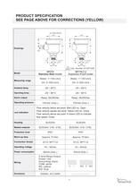
PRODUCT SPECIFICATION SEE PAGE ABOVE FOR CORRECTIONS (YELLOW) Sight Window f70 46 f70 46 78 78 Drawings PG 32 31 32 31 G1/2" f7.4 f38 G1/2" f7.4 f38 Cert. Number GYJ071446 SP210 Stainless Steel model SP170-(½) Explosion Proof model Water: 1~150 cm/s Water: 1~150 cm/s Oil: 3~300 cm/s Oil: 3~300 cm/s Ambient temp. -20 ~ 80BC -20 ~ 80BC Operating temp. -20 ~ 80BC -20 ~ 80BC Relay: 5A/250Vac Relay: 3A/250Vac 100 bar (max.) 100 bar (max.) Model Measuring range Alarm output Operating pressure Led indication Housing Flow velocity below set point- Red LED on, Open Flow velocity equals set point- Yellow...
Open the catalog to page 5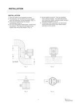
INSTALLATION INSTALLATION 4. Screw tightly to avoid. Can be installed from various angles. For best sensitivity and response speed, please install using in the demonstrated in Fig. 4 5. Installing a filter upstream can decrease liquid impurities which can reduce wear and tear on the switch. 1. Use the water-proof gasket provided 2. The distance "a" should be 4 times larger than the switches’ screw diameter. (Fig. 1) 3. The pipe is bubble free for proper functioning. (Fig. 2) 4. For not-completely-filled pipes, install from the bottom. The liquid level needs to be higher than the probe height....
Open the catalog to page 6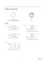
CWIRING AND CONNECTIONS 2 3 1 SENSITIVITY ALARM 4 Fig. 5 Wire terminal diagram (NPN, PNP and 1A relay output type) Fig. 6 WIRING 3-wire 3 NPN 1 4 ) ) ) 4-wire Blue 1 Brown 2 Black 3 ) ) ) 4 ) NO Fig. 7, NPN output type wiring Brown Blue Green Black Fig. 10, Relay output type wiring (NO) PNP 1 ) 3 ) 4 ) Brown 1 Blue 2 Black 3 ) ) ) 4 ) NC Fig. 8, PNP output type wiring Brown Blue Green Black Fig. 11, Relay output type wiring (NC) 5-wire Red Relay Black White Yellow Blue COM NC NO Fig. 9, Relay output type wiring 6
Open the catalog to page 7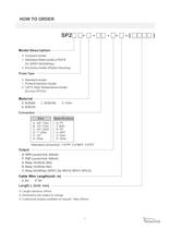
Model Description- 1: Stainless Steel model ^70X78 2: Economy model (Plastic Housing) Probe Type - 1: Probe Extension model 2: 120°C High Temperature model Cable Wire Length(unit: m) - Dimensions are subject to change Customized lengths available on request * Max.200mm
Open the catalog to page 8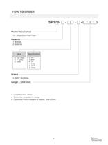
Model Description — 70 —Explosion Proof Type Dimensions are subject to change Customized lengths available on request * Max.200mm
Open the catalog to page 9
PADDLE TYPE FLOW SWITCH PRINCIPLE SECTIONAL DRAWINGS Flow Switch can detect liquid movement in pipes. When the liquid is static or nonexistent, the spring is fully extended pulling the magnet downward and opening the switch. As flow occurs and the paddle is thrusted forward 20BC~30BC (or more) the paddle will push the magnet upward and actuate the switch (closing the circuit) The length of paddle can be adjusted to the pipe's diameter. 1. O-Ring 7 2. Paddle 3. Axis 4. Reed switch 1 5. Spring 6. Magnet 5 6 7. Housing 9 8. Screw 9. Center rod 4 8 3 1" 1-1/4" 1-1/2" 2" 2-1/2" spring 3" magnet 2...
Open the catalog to page 10
FLOW CONTROL RANGE TABLE 1. The paddle length is dependent on the lowest paddle point to actuate the switch. Cut the pad- dle at appropriate pipe size mark or wherever 2. The paddle must be at a right angle to the direc- 3. The FLOW mark on the screw must be 4. Before installing the unit to a tee pipe, apply thread seal tape to the screw and then • Not recommended for 1" or smaller NPT plastic pipes. 1. The pressure and temperature ranges as shown in the catalog, must not be exceeded and also take the abrupt pressure and temperature into consid- 2. Large sudden changes in liquid temperature and...
Open the catalog to page 11
[FC/FD] Mini Float/Magnetic Float Level Switch [FG] Magnetic Float Level Transmitter [FF] Side Mounting Float Switch [FA/FB] Cable Float Level Switch [SP] Thermal Dispersion Flow Switch [SF] [PB] Paddle Flow Switch [SD] [FG] [JFR] [EB] [EC] [FC/FD] [SB] [EB] [EF] [SC] Rotary Paddle Level Switch [SA] [EG] [FA/FB] Optical Level Switch [SE] [LR] [EA] Capacitance Level Switch [EC] [FF] Pressure Level Transmitter [LR] [SA] Loop Power Indicator [SC] Vibrating Probe Level Switch [SC] [SF] Tuning Fork Level Switch [EB] RF-Capacitance / Admittance Level Switch [FC/FD] [SP] RF-Capacitance Level Transmitter...
Open the catalog to page 12All FineTek Co., Ltd. catalogs and technical brochures
 Cable Float Level Switch
16 Pages
 Side Mounting Float Switch
16 Pages
 EFX By-Pass Level Transmitter
34 Pages
 EPD Electromagnetic Flow Meter
28 Pages
 Tuning Fork Level Switch
32 Pages
 Ultrasonic Level Transmitter
8 Pages
 Temperature Transmitter
5 Pages
 Thermocouple
12 Pages
 Vibrating point level switch
14 Pages
 SA Capacitance Level Switch
18 Pages
 SE Rotary Paddle Level Switch
15 Pages
 EC Pressure Level Transmitter
12 Pages
 SQ Pressure Switch
12 Pages
 SD Optical Level Switch
2 Pages
 FF Side Mounting Float Switch
15 Pages
 FC/FD Mini Float Level Switch
28 Pages
 RF-Admittance Level Switch
11 Pages
 Optical Level Switch
13 Pages
 Rotary Paddle Level Switch
15 Pages
 Magnetic Float Level Transmitter
14 Pages
 RF-Admittance Level Transmitter
15 Pages
 Capacitance Level Switch
18 Pages
 Vibrating Probe Level Switch
10 Pages
 Pressure Level Transmitter
12 Pages
 Magnetic Float Level Switch
24 Pages
 EF By-Pass Level Transmitter
23 Pages
 Air Hammer/Pneumatic Vibrator
16 Pages
 Mini Float Level Switch
28 Pages
 Pressure Switch
12 Pages


Archived catalogs
 PID+Fuzzy Temperature Controller
23 Pages


- Valve
- Control valve
- FineTek flow meter
- Pneumatic valve
- Volume flow monitor
- Liquid flow monitor
- Pressure transmitter
- Measuring machine
- Pressure gauge
- Single-pole switch
- Analog pressure transmitter
- Waterproof flow meter
- Pneumatically-operated valve
- FineTek liquid level switch
- Level probe
- Stainless steel flow monitor
- Digital indicator
- Pressure switch