- Catalogs
- FineTek Co., Ltd.
- Electromechanical Level Measuring System
- Products
- Catalogs
- News & Trends
- Exhibitions
Electromechanical Level Measuring System

Electromechanical Level Measuring System
Catalog excerpts

Electromechanical Level Measuring System
Open the catalog to page 1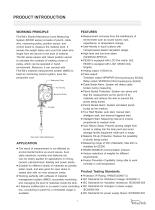
PRODUCT INTRODUCTION WORKING PRINCIPLE FineTek's Electro-Mechanical Level Measuring System (EE300 series) consists of plumb, cable wire, measuring pulley, position sensor, and control board to measure the material level. It senses the weight status and count the cable wire length from the device to the level of material. The EE series equips with robust position sensor to calculate the numbers of rotating circles of pulley, which can be operated in harsh environment. Moreover, it can connect with FineTek's material measurement system (MMS) to build an monitoring control system, save the production...
Open the catalog to page 2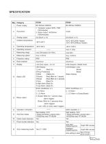
Power supply 1. Transistor output: NPN / PNP (10mm/pulse) 2. Relay output: 3A/250Vac (100mm/pulse) Analog output Operating temperature Operating pressure Measuring range Measuring speed Protection rating Body material LCM (Graphic,128x64 Dots) LCM Display: Lock Buried Break Status Display LCD (Dot matrix , 8 X 2) LED Display: 1.Lock (Red) On (Fill-Up Protection) 2.RUN (Yellow) On 3.Buried (Red) Blink for 1 second 4.Break (Red) Blink for 2 seconds 5.Auto (Blue) On 6.High Alarm (Red) On 7.Low Alarm (Red) On SPDT 3A/250Vac X 3 1. HI Alarm 2. LO Alarm 3. Buried: Blink for 1 second when alarm triggers...
Open the catalog to page 3
Activating from outside Motor limited current protection Malfunction diagnosis display Yes(alternatire of HI Alarm,Lo Alarm or Buried alarm,Break alarm) Material fill up protection Material discharge protection Intelligent start C8N1.C8N2.C801.C8E1 Frame C8N1 C7N2.C701.C7E1.C702 C7E2. Yes Yes 1200.2400.4800.9600 1200.2400.4800.9600 Baudrate 11520.14400.19200 Baudrate 19200.38400.57600 28800.57600 Yes (Measuring interval is inverse proportional to medium level) Cable wire
Open the catalog to page 4
EE300 SKETCH & DRAWING/ DIMENSION Sketch & Drawing Measuring Pulley Control Board Switching Power Supply Receiving Pulley 1/4" PT Air Intake Hole AL Base M4 Outer Case Ground M25HP1.5 Conduit Dust Brush Dust Wiper Rear View: Wiring Mechanism Front View: Electric Board & Motor Front View
Open the catalog to page 5
EE400 SKETCH & DRAWING/ DIMENSION Sketch & Drawing Retrieving Pulley Control Panel Base 1/4" PT Air Intake Hole 1/2"PF Coduit Grounding Screw Dust-Proof Device Electric system(front view) Retrieving Mechanism(back view) Front View
Open the catalog to page 6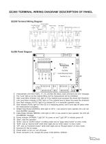
EE300 TERMINAL WIRING DIAGRAM/ DESCRIPTION OF PANEL EE300 Terminal Wiring Diagram Current signal output Relay pulse Low alarm Malfunction(Buried Break Lock) Start Contact Power supply High alarm RUN BURIED BREAK POWER Level Measuring System UP Characteristic LCD (Dot matrix , 8 × 2), provides the status, level command and error message. The “Lock” light on as the material filling and the measurement will be prohibited. High Level Alarm Indicator (HI), light on if the material level excesses the preset high threshold. Low Level Alarm Indicator (LOW), light on if the material level is below the...
Open the catalog to page 7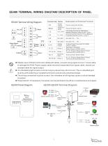
EE400 TERMINAL WIRING DIAGTAM/ DESCRIPTION OF PANEL EE400 Terminal Wiring Diagram Description of Terminal Function Power Supply Power for Motor Analog Output Analog Output Terminal 0/4-20Ma (AOUT, AGND) Operation Indication Relay Output (COM3, NO3) HI, LO, Buried, Break Alarm Output Terminal (NO1,NOM1,NC1) External Start HI, LO, Buried, Break Alarm Output Terminal (NO2,NOM2,NC2) Out_Lock In_Lock Relay 1 motor EXTERN Measure Power supply 88~264Vac Power for Moter 24Vdc Connecting Terminal for Discharging Material Protection Switch (Lock+, Lock-) Connecting Terminal for Fill up Material Protection...
Open the catalog to page 8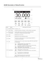
Company Name FineTek Co., Ltd. Alarm Status Indicate the status of Hi Alarm, Lo Alarm, Motor overheated Measurement Time Setting Function allows users to set the time to start measurement. This function is activated as the symbol showed. Display the current time Display the current measuring value Indicate the current value is for material height (OBJECT) or Distance (DISTANCE) Indicate the unit for current value is meter (METER), feet (FEET) or percentage “Adding number” as in number mode “Moving up” as in menu mode “Entering” to engineering password as in main menu “Reducing number” as in number...
Open the catalog to page 9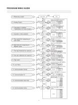
PROGRAM MING GUIDE 3: Calculation in Addition ^VJsS / Subtraction For Level Position ^ 4: Operation mode selection ~^Z^' 5: Time period for measuring at ^-N\ auto mode__/~K 6: Start Time for measuring at SMART mode The zero reference for reservoir 13: Communication baud rate Analog OutputfOP] Switch Mode.
Open the catalog to page 10
SETTING MOOE NORMAL SETTING PATTERN SETTING TANK PARAMETER OPERATION MODE DISPLAY SCHEDULE MODE TANK HEIGHT BLINO AREA HI ALARM POINT LO ALARM POINT TANK HEIGHT BLIND AREA HI ALARM POINT LO ALARM POINT Tank Parameter Setting TANK HEIGHT BLIND AREA HI ALARM POINT LO ALARM POINT TANK HEIGHT BLIND AREA HI ALARM POINT LO ALARM POINT TANK PARAMETER OPERATION MODE DISPLAY SCHEDULE MODE SETTING MENU AUTO MODE SMART MODE MANUAL MODE AUTO MODE SMART MODE MANUAL MODE Operation Mode Setting OPERATION MODE 2.3 AUTO MODE SMART MODE MANUAL MODE SETTING MENU TANK PARAMETER OPERATION MODE DISPLAY SCHEDULE MODE...
Open the catalog to page 11
SETTING PROCEDURE Caution 1.Don’t start the measurement when the silo is empty and height of silo is unknown. It will possibly lead to the plumb falling into the silo outlet and getting stuck and damaged. 2.Be sure the measuring level must be higher than bottom of silo and avoid any possibility of being stuck by conveyer, ladders, and any mechanisms, suggesting the measuring level is at least 1 meter higher than silo outlet/ conveyer. 3.Materials filling conveyer must connect with filling up protection switch so that it will prevent the damage occured by plumb got hit or buried. 4.It’s necessary...
Open the catalog to page 12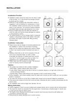
Installation Position Installation position should be away from the inlet or outlet of silo at lease 1.2 m, and prevent the damage occured by plumb got hit or buried. Reservoir or tank equipped with observation window is suggested; it will be beneficial for maintenance in future. The installation location should be away from the ladder, frame or any protrusion. The minimum distance between the EE300 center and tank wall should be 1m or more. Must be located away from the inlets flow direction to avoid the cable and hammer being damaged by material or disconnected or buried. The optimal position...
Open the catalog to page 13All FineTek Co., Ltd. catalogs and technical brochures
 Cable Float Level Switch
16 Pages
 Side Mounting Float Switch
16 Pages
 EFX By-Pass Level Transmitter
34 Pages
 EPD Electromagnetic Flow Meter
28 Pages
 Tuning Fork Level Switch
32 Pages
 Ultrasonic Level Transmitter
8 Pages
 Temperature Transmitter
5 Pages
 Thermocouple
12 Pages
 Vibrating point level switch
14 Pages
 SA Capacitance Level Switch
18 Pages
 SE Rotary Paddle Level Switch
15 Pages
 EC Pressure Level Transmitter
12 Pages
 SQ Pressure Switch
12 Pages
 SD Optical Level Switch
2 Pages
 FF Side Mounting Float Switch
15 Pages
 FC/FD Mini Float Level Switch
28 Pages
 RF-Admittance Level Switch
11 Pages
 Optical Level Switch
13 Pages
 Rotary Paddle Level Switch
15 Pages
 Magnetic Float Level Transmitter
14 Pages
 RF-Admittance Level Transmitter
15 Pages
 Capacitance Level Switch
18 Pages
 Vibrating Probe Level Switch
10 Pages
 Pressure Level Transmitter
12 Pages
 Magnetic Float Level Switch
24 Pages
 EF By-Pass Level Transmitter
23 Pages
 Air Hammer/Pneumatic Vibrator
16 Pages
 Mini Float Level Switch
28 Pages
 Pressure Switch
12 Pages


Archived catalogs
 PID+Fuzzy Temperature Controller
23 Pages


- Valve
- Control valve
- FineTek flow meter
- Temperature probe
- Pneumatic valve
- Volume flow monitor
- Liquid flow monitor
- Pressure transmitter
- FineTek level switch
- Pressure gauge
- Single-pole switch
- Waterproof flow meter
- Analog pressure transmitter
- Pneumatically-operated valve
- FineTek liquid level switch
- Level probe
- Stainless steel flow monitor
- Digital indicator
- Pressure switch