


FD-3

FD-3
The FD-3 series in-line medium pressure filters are designed for a maximum working pressure of 110 bar (1600 psi) and have been tested up to 160 bar (2300 psi). The burst pressure is 330 bar (4800 psi). The filters feature 1/2” BSP connection ports, with other thread options available upon request. The housing and bowl are made from aluminum alloy, and the seals are Buna-N, with FKM available on request. The filters can operate within a temperature range of -25°C to +120°C (-13°F to +248°F) and are compatible with fluids as per ISO 2943 standards.
Filter Media:
The filter media options include microglass fiber, cellulose, and wire mesh, with various micron ratings. The differential collapse pressure is 21 bar (300 psi).
Ordering Information:
The ordering code includes specifications for nominal size, media type, seals, connection, by-pass, and indicator options. The by-pass valve can be set to either no by-pass or 6 bar (90 psi).
Pressure Drop and Flow Rate:
The pressure drop through the filter housing is influenced by the port size and oil viscosity, while the pressure drop through the filter element is affected by the internal diameter and filter media. The total pressure drop should ideally not exceed 1.0 bar (14.5 psi).
Clogging Indicator:
The filters are equipped with visual and electrical clogging indicators. The visual indicator changes from green to red when the filter element is dirty. The electrical indicator provides an additional signal when the differential pressure reaches the set value.
Installation and Maintenance:
The filter should be installed with the bowl downward and secured properly. Ensure enough space for element replacement and that the clogging indicator is visible. During maintenance, ensure the system is off and depressurized before replacing the filter element. Used filter elements cannot be cleaned and must be disposed of as hazardous waste.
Compliance:
The FD-3 filters comply with PED 97/23/CE norm, suitable for use with group 2 fluids.
Catalog excerpts

HYDRAULIC FILTRATION FD-3 series In line medium pressure filters Technical Information Pressure: Max working 110 bar (1600 psi) (acc. to NFPA T 3.10.5.1) Test 160 bar (2300 psi) (acc. to NFPA T 3.10.5.1) Burst 330 bar (4800 psi) (acc. to NFPA T 3.10.5.1) Connection Ports: 1/2” BSP (other thread options on request) Materials: Head: Bowl: Seal: aluminium alloy aluminium alloy Buna-N (FKM on request) By-pass: No by-pass or 6 bar (90 psi) setting Filter Media: Microglass fiber Wire mesh Differential collapse pressure: 21 bar (300 psi) (acc. to ISO 2941) The Filtrec elements are tested also according to ISO 2942 and ISO 23181 Working temperature: -25°C +120°C (-13°F +248°F) Fluid compatibility (acc. to ISO 2943): Full with HH-HL-HM-HV (acc. to ISO 6743/4). For use with other fluid applications please contact Filtrec Customer Service ([email protected]).
Open the catalog to page 1
Ordering information Filter assembly no element microglass fiber ß4,5 µm ( ) >1000 microglass fiber ß7 µm ( ) >1000 microglass fiber ß12 µm ( ) >1000 microglass fiber ß18 µm ( ) >1000 microglass fiber ß27 µm ( ) >1000 cellulose ß10 µm ( ) >2 cellulose ß25µm ( ) >2 wire mesh 10 µm wire mesh 25 µm wire mesh 60 µm wire mesh 125 µm C NOMINAL SIZE ELEMENT COLLAPSE INDICATOR PORT OPTION Filter element For different thread options, please check availability with Filtrec Customer Service. INDICATOR PORT OPTION no indicator port indicator port with plug indicator port without plug when ordered with indicator...
Open the catalog to page 2
element removal Indicator port Nominal size CODE FD-3-10 FD-3-11 For different thread options please contact Filtrec Customer Service.
Open the catalog to page 3
Pressure drop diagrams The total Pressure Drop (Ap) value is obtained by adding the Ap values of filter housing and filter element at the given flow rate. This ideally should not exceed 1,0 bar (14,5 psi) and should never exceed 1/3 of the set value of the by-pass valve. PRESSURE DROP THROUGH The Pressure Drop through the filter housing is governed by the port, not the bowl length and the oil PRESSURE DROP THROUGH THE CLEAN FILTER ELEMENT The Pressure Drop through the filter element is related both to the internal diameter of the filter element and to the filter media; this value is effected...
Open the catalog to page 4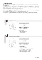
Clogging indicator The Pressure Drop (Dp) through the filter increases during the system operation due to the contaminant retained by the filter element. The filter element must be replaced when the indicator shows an alarm and before the Dp reaches the by-pass value setting. N.B. in cold start conditions a false alarm can be caused by higher oil viscosity due to low temperature; the indicator alarm must be considered at normal working temperature only. The differential clogging indicator registers the pressure upstream and downstream the filter element and activates a signal when the differential...
Open the catalog to page 5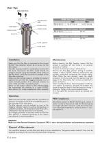
User Tips INDICATOR PORT: Visual Electric FIXING HOLES SEAL KIT IDENTIFICATION LABEL BY-PASS VALVE FIXING HOLES OU SPARE SEAL KIT PART NUMBER NBR FKM FD-3-10/11 06.021.00147 06.021.00148 BOWL TIGHTENING TORQUE FD-3-10/11 30 Nm INDICATOR TIGHTENING TORQUE Z12/Z13 90 Nm FILTER ELEMENT FILTER BOWL Make sure that the filter is connected in the correct IN-OUT flow direction (shown by an arrow on the filter head). The filter housing should be preferably mounted with the bowl downward; the filter head should be properly secured using the threaded fixing holes on the filter head; verify that no tension...
Open the catalog to page 6
Technical information may change without notice
Open the catalog to page 7All FILTREC S.p.A. catalogs and technical brochures
 F040-DMD
8 Pages
 FS-1
FS-14 Pages
 F420-D1
11 Pages
 F100-XD
8 Pages
 F160-XD
8 Pages
 F280-D1
8 Pages
 FDM-1
FDM-18 Pages
 PPP
PPP8 Pages
 PBA
PBA8 Pages
 BOLL & KIRCH
2 Pages
 WATER ABSORBENT
4 Pages
 CORELESS
4 Pages
 IFBW
IFBW12 Pages
 IFD-RHR
12 Pages
 IFD-R9
12 Pages
 IFD-R4
12 Pages
 IFS-RHR
12 Pages
 IFS-R9
12 Pages
 IFS-R4
12 Pages
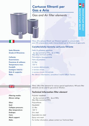 GAS AND AIR
2 Pages
 PCS
PCS4 Pages
 PMA
PMA8 Pages
 PCH
PCH4 Pages
 PCP
PCP8 Pages
 INDICATORS
16 Pages
 FT
FT8 Pages
 FL
FL4 Pages
 FB-1
FB-14 Pages
 FVR-7
FVR-78 Pages
 FS-7
FS-78 Pages
 FR-8
FR-88 Pages
 FR-1
FR-112 Pages
 FCR-7
FCR-712 Pages
 FA-4
FA-48 Pages
 FA-2
FA-28 Pages
 FA-1
FA-18 Pages
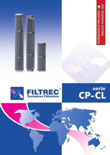 CP-CL SERIES
4 Pages
- Liquid filter
- Filter with cartridge
- Filter cartridge
- Industrial use filter
- Fine filter cartridge
- Water pre-filter
- Cartridge filter housing
- Water filter cartridge
- Liquid filter housing
- Hydraulic filter
- Liquids level gauge
- Basket filter
- Analog indicator
- Pleated filter cartridge
- Sight glass level indicator
- Self-backwashing filter
- Vertical filter
- Integrated indicator