- Catalogs
- FIBRO GmbH
- USER‘S GUIDE - MANIFOLD SYSTEM 2495.1092672.XXXX.XXX
- Company
- Products
- Catalogs
- News & Trends
- Exhibitions
USER‘S GUIDE - MANIFOLD SYSTEM 2495.1092672.XXXX.XXX
1 /8Pages

USER‘S GUIDE - MANIFOLD SYSTEM 2495.1092672.XXXX.XXX
1 /8Pages
Catalog excerpts

OPERATING AND MAINTENANCE INSTRUCTIONS MANIFOLD SYSTEM 2495.1092672.XXXX.XXX MANIFOLD-CYLINDER 2495.1092672.2104.700 2495.1092672.2104.800 2195.1092672.2202.100 2195.1092672.2202.200 MANIFOLD SYSTEM ACCESSORIES 2495.00. MEMBER OF THE LÄPPLE GROUP
Open the catalog to page 1
OPERATING AND MAINTENANCE INSTRUCTIONS MANIFOLD SYSTEM 1 PARTS LIST Control fitting 6 Quick connector, plug 6 Quick connector, plug 10 Pressure gauge Connection nipple 11 Oval head screw M5x8 Diaphragm pressure switch (optional) Gauging coupling (optional) WPM sensor (optional) Benennung Grundkörper Gehäuse Manometer 0-400 bar Entlüftungsventil G1/4 Verschlusskappe Schnellkupplung, Stecker Usit-Ring G1/4 Verschlussschraube G1/4 Verschlussschraube G1/8 Verbindungsnippel Membrandruckschalter (Optional) Messkupplung (Optional) WPM Sensor (Optiopnal) Linsenkopfschraube M5x8 xxx beschriftet...
Open the catalog to page 2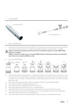
TOOLS REQUIRED SAFETY INSTRUCTIONS According to the Pressure Devices Directive 2014/68/EU, the components listed in these operating instructions may only be commissioned, maintained, repaired or overhauled by appropriately instructed and trained personnel, or by FIBRO. Failure to observe the operating instructions can lead to accidents or injuries, for which FIBRO GmbH shall have no liability. FIBRO is not liable if fittings that are not original FIBRO fittings or fastening, accessory, and attachment parts that are not released by FIBRO are used. 3.1 Only use original FIBRO parts. max. 1,6m/s...
Open the catalog to page 3
OPERATING AND MAINTENANCE INSTRUCTIONS MANIFOLD SYSTEM 3.10 Never replace the safety valve in the control fitting and/or in the manifold with a normal blind plug. 3.11 The torques specified for the blind plugs, safety valve and manifold cylinders must be observed (for more, see Table 1 in Chapter 7). 3.12 Assembly and disassembly of manifold cylinders and/or blind plugs may require high forces; these should only be assembled or disassembled with appropriate and approved mounting tools. The manifold should therefore be adequately fixed in place and secured against slipping. 3.13 Individual parts...
Open the catalog to page 4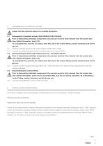
DISASSEMBLING THE MANIFOLD SYSTEM Always affix the manifold system to a suitable foundation. Disassembly of manifold cylinder 2495.1092672.2104.700/.800. Prior to dismounting individual components, the pressure must be fully released from the system (see also: Safety Information, point 3.2). To accomplish this, turn the air release valve (Pos. O) on the control fitting counter-clockwise and let the gas out. 5.1.1 Carefully compress the piston rods of the manifold cylinders with a mallet. 5.1.2 Unscrew the manifold cylinders counter-clockwise using a lock wrench SW 32. 5.2 Disassembling the blind...
Open the catalog to page 5
OPERATING AND MAINTENANCE INSTRUCTIONS MANIFOLD SYSTEM 7 ASSEMBLING THE MANIFOLD SYSTEM Before assembling the manifold, always check the exposed holes for damage to the sealing surfaces and/or threads; also check for any foreign objects that may have fallen into the manifold. The torques specified in Table 1 of these operating instructions for the assembly of the manifold cylinder and the blind plugs must be observed. 7.1 Assembling the manifold cylinders Lubricate the Viton O-ring (Pos. K) of the manifold cylinder well. Carefully screw the manifold cylinder by hand clockwise into the manifold....
Open the catalog to page 6
FILLING THE MANIFOLD SYSTEM For filling the manifold system, we recommend the additional use of the cylinder pressure reducer 2480.00.32.07.xx, since the required filling pressure is preset there and overfilling of the system is thus avoided. 8.1 The shutoff valve (pos. T) on the filling hose 2480.00.31.02 and the venting valve (pos. O) on the filling and control fitting must be closed (turn clockwise). 8.2 Plug the filling hose connector onto the quick coupling (pos. P) of the filling and control fitting. 8.3 Open the nitrogen cylinder using the knob (Pos. Z). Set the desired fill pressure on...
Open the catalog to page 7
FIBRO GMBH Business Unit Standard Parts Läpple Automotive Fibro Läpple Technology LOCATIONS FIBRO France Sarl FIBRO INDIA Département Eléments normalisées Business Area Standard Parts Business Area Standard Parts 9 Changi South Street 3, #07-04 Plot No: A-55, Phase II, Chakan Midc, Taluka Khed, Pune – 410 501 [email protected] FIBRO KOREA Co., LTD. FIBRO Inc. FIBRO (Shanghai) Business Area Standard Parts Bucheon-si, Gyeonggi-do Pilot Free Trade Zone Aleja Armii Krajowej 220 Pawilon AG piętro 3/ pokój 306 MEMBER OF THE LÄPPLE GROUP
Open the catalog to page 8All FIBRO GmbH catalogs and technical brochures
 FIBRO STANDARD PARTS YOUR SYSTEM PARTNER
1364 Pages
 Flex Cam Unit
88 Pages
 RECIRCULATING BALL BUSHES
12 Pages
 THE CLEVER OPTION PILLAR CAM
2 Pages
 AERIAL CAM UNIT 2016.27.
38 Pages
 Standard parts
1355 Pages
 GROUND PRECISION COMPONENTS
247 Pages
 Guide Elements
330 Pages
 NUOVI PRODOTTI NELL´AREA CURSORI
197 Pages
 COMPOSITE PLATE SYSTEM
32 Pages
 Composite Plate System
32 Pages
 Catalog PDF (Peripherie)
63 Pages
 Catalog PDF (Elastomer)
33 Pages
 Catalog PDF (Fibrochemie)
21 Pages
 Standard Parts SYNOPSIS
32 Pages


Archived catalogs
 Projection Planning Manual
64 Pages
 In-Die Tapping Units (FTU)
12 Pages
 2490.14. Compact gas springs
6 Pages
 Spacer for die release
4 Pages
 BOLT LOCK SYSTEM
16 Pages
 ROTARY TABLES
7 Pages
 Spring Plungers
4 Pages
 Pneumatic transporters
4 Pages
 Electro-mechanical transporters
12 Pages
 Standard Parts SYNOPSIS
16 Pages


- Rail conveyor
- Transport rail conveyor
- Belt conveyor
- Horizontal conveyor
- Clamping device
- Roller conveyor
- Spring
- Metal spring
- Wheel type roller
- Lifting eye bolt
- Compression spring
- Pin
- Feed conveyor
- Temperature monitoring module
- Clamping element
- Gas spring
- Metal pin
- Conveyor system
- Screw-in lifting point
- Steel wheel type roller