- Catalogs
- FIBRO GmbH
- Projection Planning Manual
- Company
- Products
- Catalogs
- News & Trends
- Exhibitions
Projection Planning Manual
1 /64Pages

Projection Planning Manual
1 /64Pages
Catalog excerpts

FIBROTOR ELECTROMECHANICAL UNIVERSAL ROTARY TABLES
Open the catalog to page 1
This document has been created by FIBRO GmbH Rotary Table Division Postfach 11 20 74183 Weinsberg, Germany WeidachstraGe 41 -43 T +49(0)7134 / 73 - 0 F +49(0)7134 / 73 - 218 [email protected] www.fibro.de © FIBRO GmbH All rights to this document are subject to the copyright of FIBRO GmbH. This document may not be copied or reproduced, either in full or in part, without the prior written permission by FIBRO GmbH. This document is intended only for the user of the described components. "FIBROTOR Electromechanical Universal Rotary Tables" project planning manual Edition v2 2018
Open the catalog to page 3
1 FIBROTOR at a glance The FIBROTOR rotary table series is designed for tasks that require fast indexing with optimised sequences of movement. Extremely long service lives, freedom from maintenance and very fast cycle times with the highest possible precision are properties of importance for every production facility. FIBROTOR rotary tables combine all these features and, as an additional highlight, has up to five years warranty. FIBROTOR rotary tables have been used successfully automation constructions as well as for light cutting applications. 1.1 Areas of application of the rotary table The...
Open the catalog to page 8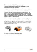
2 Overview of the FIBROTOR product range The FIBROTOR rotary table is divided into three classes based on various properties, functions and area of applications: The highly standardised universal rotary table FIBROTOR ER represents the first class. This table shines due to extremely short delivery times, special price attractiveness and long service life. The second class of the product range is formed by the premium version, the FIBROTOR EM. The premium type offers special designs according to customer desire, guarantees the highest speeds and shortest indexing times, as well as the selection...
Open the catalog to page 9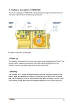
3 Technical description of FIBROTOR The structural design of FIBROTOR is characterised by a rigid mechanical structure. The basic unit consists of the following components: Mounting holes Fig.: Basic components of rotary table 3.1 Table top The table top is operated with various motor types, gearboxes and control cams. This means that the rotational movements of the table top can be performed in any direction, however using the angle preset by the control cam. 3.2 Bearing The table top has a large-dimensioned bearing with both axial and radial initial preloaded, while guaranteeing high axial...
Open the catalog to page 10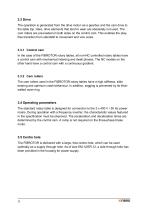
3.3 Drive The operation is generated from the drive motor via a gearbox and the cam drive to the table top. Here, drive elements that tend to wear are absolutely not used. The cam rollers are pre-loaded on both sides on the control cam. This enables the playfree transition from standstill to movement and vice versa. 3.3.1 Control cam In the case of the FIBROTOR rotary tables, all non-NC controlled rotary tables have a control cam with mechanical indexing and dwell phases. The NC models on the other hand have a control cam with a continuous gradient. 3.3.2 Cam rollers The cam rollers used in the...
Open the catalog to page 11
3.6 Air purge The rotary table has a connection for the air purge between the housing and the table top (for position and connection thread see the dimensional drawing). The necessary compressed air must be provided by the supply facilities of the operator. The air purge must be regulated and purified by a control valve with a filter. The maximum permitted air purge pressure is 7 psi / 0.5 x 10⁵ Pa / 0.5 bar. Please note! If a pressure of 7 psi / 0.5 x 10⁵ Pa / 0.5 bar is exceeded, serious damage to the rotary table can occur. The air purge must conform to quality class 4 according to DIN-ISO...
Open the catalog to page 12
The layout is designed for a service life of 20,000 operating hours MTTF. The service life of the motor brake depends on the number of switching cycles per minute, the indexing time of the rotary table, the speed of the motor and the ambient temperature. At the standard brake motor the service life of the motor brake amounts to 10 - 20 million switching cycles. The readjustment term amounts to 3 - 5 million switching cycles (see the operating instructions). Frequent emergency stop operation can reduce the service life. A soft start after an emergency stop can be implemented using frequency inverters...
Open the catalog to page 13
The purpose of the rotary table is to be mounted in other machines or in other partly completed machinery or equipment or to be assembled with them. It must not be subjected to loads above its maximum limits. In addition, the standard version is not suitable for the following: ■ Operation in mobile or portable systems, on ships or in aircraft ■ Operation in life support systems ■ Operation in residential housing ■ Operation beyond the limits of the specified performance data and operating parameters ■ Use in explosive atmospheres ■ Use in vacuum spaces Corresponding special designs of the FIBROTOR...
Open the catalog to page 14
5 Rotary tables with fix division: FIBROTOR ER, EM and RT 5.1 Technical description 5.1.1 Cam roller gearbox The ER, EM and RT rotary tables have a fix, pre-set division. They have a control cam with a discontinuous gradient.
Open the catalog to page 15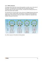
5.1.2 Motion sequence The design of the control cam ensures that operation is smooth, even in the event of high loads. The indexing time can be taken from the indexing time tables in accordance with the mass moment of inertia. The data for the indexing time (ts in s) refer to the actual motion duration. The discontinuous movement path on the control cam of FIBROTOR ER, EM and RT result in an uneven rotating motion of the table top. Indexing and dwell phases are differentiated. The time for the control cam rotation is divided into a stipulated ratio between indexing and dwell time. Fig.: Motion...
Open the catalog to page 16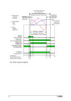
1 Umdrehung der Steuerkurve 1 turn of control cam Start) mpuls Start pulse Impiisicn de oemarrage Antnebsmotor “Bn" Drive motor "On” Motetr dentranament en marche Schattterier "drerif' Index table "tuning" Le plateau toume S10 "Schaltteller im Stillstand" S10 "Index table stationary" S10 le plateau est arete S12 "Motor Aus" S12 "Motor off S12 "Moteur hors droit" Ablaufdiagramm Running sequence diagram Diagramme des mouvements
Open the catalog to page 17All FIBRO GmbH catalogs and technical brochures
 FIBRO STANDARD PARTS YOUR SYSTEM PARTNER
1364 Pages
 Flex Cam Unit
88 Pages
 RECIRCULATING BALL BUSHES
12 Pages
 THE CLEVER OPTION PILLAR CAM
2 Pages
 AERIAL CAM UNIT 2016.27.
38 Pages
 Standard parts
1355 Pages
 GROUND PRECISION COMPONENTS
247 Pages
 Guide Elements
330 Pages
 NUOVI PRODOTTI NELL´AREA CURSORI
197 Pages
 COMPOSITE PLATE SYSTEM
32 Pages
 Composite Plate System
32 Pages
 Catalog PDF (Peripherie)
63 Pages
 Catalog PDF (Elastomer)
33 Pages
 Catalog PDF (Fibrochemie)
21 Pages
 Standard Parts SYNOPSIS
32 Pages


Archived catalogs
 In-Die Tapping Units (FTU)
12 Pages
 2490.14. Compact gas springs
6 Pages
 Spacer for die release
4 Pages
 BOLT LOCK SYSTEM
16 Pages
 ROTARY TABLES
7 Pages
 Spring Plungers
4 Pages
 Pneumatic transporters
4 Pages
 Electro-mechanical transporters
12 Pages
 Standard Parts SYNOPSIS
16 Pages


- Rail conveyor
- Transport rail conveyor
- Belt conveyor
- Horizontal conveyor
- Clamping device
- Roller conveyor
- Spring
- Metal spring
- Lifting eye bolt
- Wheel type roller
- Compression spring
- Pin
- Feed conveyor
- Temperature monitoring module
- Clamping element
- Gas spring
- Metal pin
- Conveyor system
- Screw-in lifting point
- Steel wheel type roller