- Catalogs
- FIBRO GmbH
- Flex Cam Unit
- Company
- Products
- Catalogs
- News & Trends
- Exhibitions
Flex Cam Unit
1 /88Pages

Flex Cam Unit
1 /88Pages
Catalog excerpts

Flex Cam Hydraulic cylinders and tool slides for tool and mould-making and machinery construction
Open the catalog to page 1
Contents Page Introduction 5 - 6 Description 6 - 7 Stroke rate/Capacity and output 8 Funktion 9 Power Unit/Cam Unit combinations 10 Selecting the components 11 - 14 15 - 47 Dimensions and Order No Cam Units Force Cylinders 15–40–60–90–150 kN 16-22-30-36-42 Force Cylinders with base plate 15–40–60–90–150 kN 17-23-31-37-43 Compact Cams 15–40–60–90–150 kN 18-34-32-38-44 Power Units 15–40–60–90–150 kN 20-28-34-40-46 Flange Cam 26-27 Electric hydraulic pump Electric hydraulic pump Quick-release couplings Accessories Connecting hoses Threaded couplings...
Open the catalog to page 3
Flex Cam General System safety, reliability and functionality can be ensured by supplying FIBRO with the application data and drawings of the installation arrangements for checking. Please note that the number of the threaded connections and the hose lengths for installation in the system must be determined. Assembly, commissioning, maintenance and servicing of the Flex Cam system require special knowledge and may only be carried out by FIBRO trained, specialist personnel. You can order the work to be carried out by a FIBRO customer service engineer, to be invoiced in accordance with our installation...
Open the catalog to page 4
Power Unit Accumulator Power Cylinder Burst guard Nitrogen charge connection Piston Oil Nitrogen charge Hydraulic hose connection Hydraulic hose Piston Adapter plate Piston rod Piston rod guide, sealing (nitrogen spring) Nitrogen charge Nitrogen charge connection Bleeding screw Duplex piston (sealing nitrogen and oil charges) Hydraulic hose connection Stroke Safety hose Force Cylinder Limit of stroke (external)
Open the catalog to page 5
The hydraulic cam system is the ideal com-ponent for executing linear motions at any point in the available space. Power Unit The system is increasingly atng used in tool making, in particular, to drive drawing, moulding, cutting and drilling operations where conventional slides cannot be used due to lack of space or inconvenient position. The Power Unit consists of the following components: • Power Cylinder • Accumulator • Adapter plate The Power Cylinder is filled with oil at one end, while the machine that executes the stroke is at the opposite end. The working motion is generated by the cam...
Open the catalog to page 6
Charging fittings Nitrogen gas: The Accumulator and Cam Unit can be charged with the gas spring filling charge 2480.00.32.21. The Power Cylinder starts the piston rod of the Compact Cam moving when pressurised. The slide is returned by external gas springs. Two pillars with guideways prevent the tool holder plate rotating. The clearance in the guides is 0.01 - 0.03 mm. Hydraulic system: The system is filled and vented using the oil filling unit 2018.00.30. Filling and venting of the system is described in detail in the user manual supplied with the system. Hydraulic connection The Compact Cam...
Open the catalog to page 7
Flex Cam Stroke rate The stroke rate is dependent on the minimum flow opening, the volume of oil and the working and return pressures. The connecting openings allow a working stroke rate of up to 0.8 m/s. Although this is limited by the extent to which the system heats up due to the high stroke rates. The system temperature should not exceed 60 °C. The forces listed in table 1 below are applicable for the following nitrogen gas pressures: As the volume of the hydraulic oil increases when the system temperature rises, the cam unit no longer returns completely to its stroke starting position due...
Open the catalog to page 8
Pressure ratios in the system The individual components of the Flex Cam System described above interact as follows: a he Power Cylinder is actuated by the stroke of the T press. PWork+ PRetract Normal working stroke Blocking slide b nce the pressure build-up in the Flex Cam exceeds O the preset pressure in the Force Cylinder, the Force Cylinder extends. POil = PWork+ PRetract c hen the Force Cylinder reaches its working position, W the pressure in the system rises to match the pressure in the Accumulator. The rest of the displaced volume of oil is then held in the Accumulator (Power Cylinder...
Open the catalog to page 9
Flex Cam Possible combinations Power Unit with Cam Unit Cam Unit leading One or more Cam Units driven with delay If a stroke of the Cam Unit is required before the tool actually reaches its working position, this can be achieved by incorporating a gas spring. The press stroke actuates a gas spring which, in turn, actuates the Power Unit, since its prestressing force is higher than the nominal force of the Power Unit. A time delay, and thus a variable working sequence for the Cam Units, can be achieved by combining two different strokes. The first Power Unit to be actuated executes the first step....
Open the catalog to page 10
Flex Cam Selecting the components The component sizes are explained step by step below with regard to the forces required, stroke length and the number of operations. Step 1: Size of the Cam Unit Calculate the force required for the operation to be carried out. The Cam Unit used should provide sufficient force to execute the operation. If the force required cannot be precisely calculated, we recommend that you use a larger Cam Unit. Force required (kN) 0 - 15 15 - 40 40 - 60 60 - 90 90 - 150 Force required: kN Cam Unit size: Example: f the force required is 22 kN, then a 40 kN...
Open the catalog to page 11
Flex Cam Power unit selection table Cam Unit force (kN) 15
Open the catalog to page 12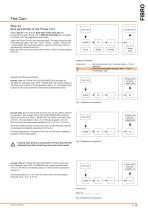
Flex Cam Step 4a Size and stroke of the Power Unit Power Unit Follow step 4a if one to three Cam Units of the same size are connected to a given Power Unit. If different Cam Units are connected to a Power Unit, then step 4b should be used. Select the Power Unit from the following table. The table should be read in the following order: Cam Unit – force – stroke – number – Power Unit – stroke length. We recommend that no more than three Cam Units be connected to a single Power Unit. Make sure that you do not exceed the maximum Cam Unit stroke speed (0.8 m/s). Stroke used Selection flowchart Power...
Open the catalog to page 13All FIBRO GmbH catalogs and technical brochures
 FIBRO STANDARD PARTS YOUR SYSTEM PARTNER
1364 Pages
 RECIRCULATING BALL BUSHES
12 Pages
 THE CLEVER OPTION PILLAR CAM
2 Pages
 AERIAL CAM UNIT 2016.27.
38 Pages
 Standard parts
1355 Pages
 GROUND PRECISION COMPONENTS
247 Pages
 Guide Elements
330 Pages
 NUOVI PRODOTTI NELL´AREA CURSORI
197 Pages
 COMPOSITE PLATE SYSTEM
32 Pages
 Composite Plate System
32 Pages
 Catalog PDF (Peripherie)
63 Pages
 Catalog PDF (Elastomer)
33 Pages
 Catalog PDF (Fibrochemie)
21 Pages
 Standard Parts SYNOPSIS
32 Pages


Archived catalogs
 Projection Planning Manual
64 Pages
 In-Die Tapping Units (FTU)
12 Pages
 2490.14. Compact gas springs
6 Pages
 Spacer for die release
4 Pages
 BOLT LOCK SYSTEM
16 Pages
 ROTARY TABLES
7 Pages
 Spring Plungers
4 Pages
 Pneumatic transporters
4 Pages
 Electro-mechanical transporters
12 Pages
 Standard Parts SYNOPSIS
16 Pages


