
- Catalogs
- FIBRO GmbH
- COMPOSITE PLATE SYSTEM


- Company
- Products
- Catalogs
- News & Trends
- Exhibitions
COMPOSITE PLATE SYSTEM

COMPOSITE PLATE SYSTEM
The composite plate system by FIBRO GmbH is designed to improve the functionality and maintenance of gas compression springs in tooling applications. It allows for external monitoring, adjustment, filling, and discharging of gas pressure, enhancing maintenance ease, safety, and quality.
Key Features
- Eliminates hose connections between gas pressure springs.
- Ensures leak-tightness with frequent installations or removals.
- No special tools required for setup and disassembly.
- Complies with the Pressure Equipment Directive 2014/68/EU.
Design and Installation
Ideal for environments with limited space, the system includes customer-specific designs and individual machining. Gas springs can be fastened using bottom-side threaded bores, with sealing via connecting nipples or flat gaskets.
Design Instructions
- Avoid blind bore holes for easy cleaning.
- Maintain a minimum distance of 5 mm to deep-hole bores.
- Ensure plate parallelism through machine grinding.
- Brush out deep-hole bores to remove dirt particles.
Safety Information
Release pressure completely at the vent valve before disassembly. Only FIBRO personnel should rework gas pressure springs and control fittings.
Technical Specifications
- Pressure medium: Nitrogen N2
- Max. filling pressure: 150 bar
- Min. filling pressure: 50 bar
- Working temperature: 0°C to +80°C
- Temperature-related force increase: ±0.3%/°C
- Max. piston speed: 1.6 m/s
Product Variants
Includes various gas spring models like standard, powerline, and heavy-duty, each with specific order numbers, dimensions, and force specifications.
Specifications and Standards
FIBRO gas springs comply with PED 2014/68/EU standards, ensuring a minimum of 2 million full strokes at maximum permissible limits.
Safety Features
- Overstroke Protection: Patented system for safe gas escape.
- Return Stroke Protection: Special guides and safety stop.
- Overpressure Protection: Safety collar destruction for gas release.
- Flexible Guides: Reduces friction and temperature.
- Safe Hose Connections: Dual SealTM System for leak-tightness.
- Wireless Monitoring: Alerts for potential issues.
- Protected Piston Rods: Concertina Shrouds for protection.
Benefits
- Guaranteed safety and reliability.
- Safe working environment.
- Extended service life.
- Leak-tight connections.
- Preventative quality assurance.
Recommendations
Replace the spring after a protection function is triggered. Perform maintenance only when the gas spring is depressurized.
Contact Information
FIBRO GmbH, August-Läpple-Weg, 74855 Hassmersheim, Germany. Phone: +49 6266 73-0, Email: [email protected], Website: www.fibro.com
Catalog excerpts

COMPOSITE PLATE SYSTEM FIBRO GMBH Geschäftsbereich Normalien LÄPPLE AUTOMOTIVE FIBRO LÄPPLE TECHNOLOGY
Open the catalog to page 1
COMPOSITE PLATE SYSTEM GENERAL The connection of gas compression springs in one or more systems offers the user the option to monitor the gas pressure of the gas compression springs outside the tool, adjusting them as required, filling them and discharging them. The advantages of the composite system lie in the ease of maintenance, safety and quality improvement of the gas pressure spring application in the tool. Composite plate system Composite plate systems are advantageously used where, due to minimal space conditions, there is no option to connect the gas compression springs via tubing in...
Open the catalog to page 3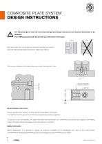
COMPOSITE PLATE SYSTEM DESIGN INSTRUCTIONS The following figures show the most important general design instructions and minimum dimensions to be observed. Your FIBRO specialist staff will provide you with further information. correct Blind bore holes are to be avoided as otherwise impurities can settle or chip-free cleaning after plate production is made more difficult. The minimum distance to the deep-hole bore must not be less than 5 mm. General design instructions During manufacturing, attention must be paid to the parallelism of the plate. It is therefore machine-ground to achieve the corresponding...
Open the catalog to page 4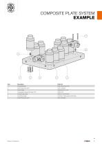
COMPOSITE PLATE SYSTEM EXAMPLE Composite plate Socket head cap screw Control fitting Compression Spring Set Screw G1/8 Connecting nipple mounted in spring base/control fitting Socket head cap screw
Open the catalog to page 5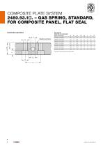
COMPOSITE PLATE SYSTEM 2480.93.1□. – GAS SPRING, STANDARD, FOR COMPOSITE PANEL, FLAT SEAL Connection geometry Gas springs Order No. for composite plate connection Sealing surface * Number of gas spring mounting holes
Open the catalog to page 6
COMPOSITE PLATE SYSTEM 2480.93.1□. – GAS SPRING, STANDARD, FOR COMPOSITE PANEL, FLAT SEAL m (n*) Flex Guide View/Design gas spring with flat seal Technical information Pressure medium: Nitrogen Working temperature: Max. recommended extensions per minute: Ordering Code (example): Temperature related force increase: Spring force in daN at 150 bar/+20°C Order No. Initial spring force at full stroke (s) / * Number of gas spring mounting holes
Open the catalog to page 7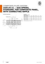
COMPOSITE PLATE SYSTEM 2480.94.1□. – GAS SPRING, STANDARD, FOR COMPOSITE PANEL, WITH CONNECTING NIPPLE Connection geometry Sealing surface Gas springs Order No. for composite plate connection * Number of gas spring mounting holes
Open the catalog to page 8
COMPOSITE PLATE SYSTEM 2480.94.1□. – GAS SPRING, STANDARD, FOR COMPOSITE PANEL, WITH CONNECTING NIPPLE V>max Flex Guide View/Design X - gas spring Technical information Working temperature: Temperature related force increase: Max. recommended extensions per minute: Pressure medium: Nitrogen e øb X Ordering Code (example): Spring force in daN at 150 bar/+20°C Order No. Initial spring force full stroke (s) / * Number of gas spring mounting holes
Open the catalog to page 9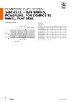
COMPOSITE PLATE SYSTEM 2487.93.12. – GAS SPRING, POWERLINE, FOR COMPOSITE PANEL, FLAT SEAL Connection geometry Gas springs Order No. for composite plate connection Sealing surface * Number of gas spring mounting holes
Open the catalog to page 10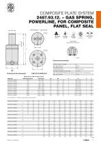
COMPOSITE PLATE SYSTEM 2487.93.12. – GAS SPRING, POWERLINE, FOR COMPOSITE PANEL, FLAT SEAL View/Design X - gas spring Flex Guide View/Design gas spring with flat seal Technical information Pressure medium: Nitrogen Max. filling pressure: Min. filling pressure: Working temperature: Temperature related force increase: Max. recommended extensions per minute: Max. piston speed: X Ordering Code (example): m M6 x 6 tief M6 x 8 tief M8 x 6 tief M8 x 6 tief M8 x 6 tief M8 x 6 tief M8 x 12 tief M10 x 12 tief M10 x 13 tief M12 x 16 tief full stroke (s) / * Number of gas spring mounting holes s l lmin....
Open the catalog to page 11
COMPOSITE PLATE SYSTEM 2487.94.12. – GAS SPRING, POWERLINE, FOR COMPOSITE PANEL, WITH CONNECTING NIPPLE Connection geometry * Number of gas spring mounting holes Sealing surface Gas springs Order No. for composite plate connection
Open the catalog to page 12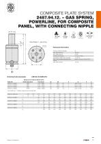
COMPOSITE PLATE SYSTEM 2487.94.12. – GAS SPRING, POWERLINE, FOR COMPOSITE PANEL, WITH CONNECTING NIPPLE V>max Flex Guide Technical information Pressure medium: Nitrogen Max. filling pressure: Min. filling pressure: Working temperature: Temperature related force increase: Max. recommended extensions per minute: Max. piston speed: e øb X Ordering Code (example): Spring force in daN at 150 bar/+20°C Order No. 2487.94.12.04200. 2487.94.12.06600. 2487.94.12.09500. 2487.94.12.20000. 1) at m M8 x 12 tief M10 x 12 tief M10 x 13 tief M12 x 16 tief full stroke (s) / * Number of gas spring mounting holes...
Open the catalog to page 13
COMPOSITE PLATE SYSTEM 2488.93.13. – GAS SPRING, HEAVY DUTY, FOR COMPOSITE PANEL, FLAT SEAL Connection geometry 0 d 1 -0,2 Gas springs Order No. for composite plate connection Sealing surface * Number of gas spring mounting holes
Open the catalog to page 14
COMPOSITE PLATE SYSTEM 2488.93.13. – GAS SPRING, HEAVY DUTY, FOR COMPOSITE PANEL, FLAT SEAL A Flex Guide View/Design gas spring with flat seal Technical information Pressure medium: Nitrogen Working temperature: Temperature related force increase: Max. recommended extensions per minute: ca. 15 up to 100 (at 20°C) Ordering Code (example): Spring force in daN bei 150 bar/+20°C Order No. Initial spring force full stroke (s) / * Number of gas spring mounting holes
Open the catalog to page 15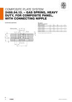
COMPOSITE PLATE SYSTEM 2488.94.13. – GAS SPRING, HEAVY DUTY, FOR COMPOSITE PANEL, WITH CONNECTING NIPPLE Connection geometry Gas springs Order No. for composite plate connection 2488.94.13.02400. * Number of gas spring mounting holes Sealing surface
Open the catalog to page 16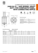
COMPOSITE PLATE SYSTEM 2488.94.13. – GAS SPRING, HEAVY DUTY, FOR COMPOSITE PANEL, WITH CONNECTING NIPPLE A Flex Guide Working temperature: Temperature related force increase: Max. recommended extensions per minute: Pressure medium: Nitrogen Ordering Code (example): Spring force in daN at 150 bar/+20°C Order No. Initial spring force full stroke (s) / * Number of gas spring mounting holes
Open the catalog to page 17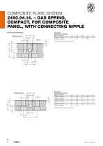
COMPOSITE PLATE SYSTEM 2490.94.14. – GAS SPRING, COMPACT, FOR COMPOSITE PANEL, WITH CONNECTING NIPPLE Connection geometry Gas springs Order No. for composite plate connection * Number of gas spring mounting holes Sealing surface Sealing surface Gas springs Order No. for composite plate connection * Number of gas spring mounting holes
Open the catalog to page 18All FIBRO GmbH catalogs and technical brochures
 FIBRO STANDARD PARTS YOUR SYSTEM PARTNER
1364 Pages
 Flex Cam Unit
88 Pages
 RECIRCULATING BALL BUSHES
12 Pages
 THE CLEVER OPTION PILLAR CAM
2 Pages
 AERIAL CAM UNIT 2016.27.
38 Pages
 Standard parts
1355 Pages
 GROUND PRECISION COMPONENTS
247 Pages
 Guide Elements
330 Pages
 NUOVI PRODOTTI NELL´AREA CURSORI
197 Pages
 Composite Plate System
32 Pages
 Catalog PDF (Peripherie)
63 Pages
 Catalog PDF (Elastomer)
33 Pages
 Catalog PDF (Fibrochemie)
21 Pages
 Standard Parts SYNOPSIS
32 Pages


Archived catalogs
 Projection Planning Manual
64 Pages
 In-Die Tapping Units (FTU)
12 Pages
 2490.14. Compact gas springs
6 Pages
 Spacer for die release
4 Pages
 BOLT LOCK SYSTEM
16 Pages
 ROTARY TABLES
7 Pages
 Spring Plungers
4 Pages
 Pneumatic transporters
4 Pages
 Electro-mechanical transporters
12 Pages
 Standard Parts SYNOPSIS
16 Pages


