
- Catalogs
- FIBRO GmbH
- CAM UNITS - 2016.24. / 2016.24./ 2016.207./ 2016.208


- Company
- Products
- Catalogs
- News & Trends
- Exhibitions
CAM UNITS - 2016.24. / 2016.24./ 2016.207./ 2016.208

CAM UNITS - 2016.24. / 2016.24./ 2016.207./ 2016.208
The document provides an overview of FIBRO's operations, emphasizing their engineering capabilities, customer-specific services, and emergency contacts. It underscores the company's dedication to quality and customer satisfaction.
FIBRO operates from Hassmersheim and Weinsberg plants, producing a wide range of standard parts for global dispatch. Their products serve machine tool, mechanical, and systems engineering needs, including die sets, precision components, and hydraulic cam systems.
FIBRO is a leader in rotary tables, offering various types like FIBROPLAN®, FIBRODYN®, FIBROMAX®, FIBROTAKT®, and FIBROTOR®. These tables are used across industries, from automotive to solar energy, and come in various sizes for different applications.
FIBRO has a strong international presence with branches in multiple countries and a network of representatives and service stations worldwide. The company is ISO 9001:2000 and ISO 14001 certified, ensuring high-quality standards and environmental responsibility.
FIBRO is committed to quality assurance, with rigorous testing from raw materials to finished products. This dedication ensures long-term customer support in safety, cost-effectiveness, and quality.
FIBRO employs advanced technology for quality assurance, including shape testing equipment that evaluates roundness, concentricity, straightness, and rectangularity. Materials undergo microscopic investigation and spectral analysis to ensure correct chemical composition. The hardening process is meticulously documented, and hardness testing is conducted on every batch. Final precision tests are conducted in a controlled environment at 20ºC.
FIBRO offers a comprehensive cam unit portfolio, with an online configurator to assist in selecting the appropriate cam unit. The configuration process involves selecting the angle, cam unit type, and dimensions of the working surface, with additional parameters like working stroke, force, and retraction force.
The document provides detailed specifications for various cam units, ensuring they meet industry standards and are suitable for a range of applications.
FIBRO's cam unit program offers solutions for diverse applications. The design of cam units is crucial for ensuring longevity and reliability, considering factors like working force, environmental conditions, and tool dynamics.
The document includes a glossary of terms and parameters related to cam units, aiding in understanding the technical aspects of cam unit design and operation.
This section provides definitions for various technical parameters used in the document, crucial for understanding the specifications and calculations related to cam unit design and operation.
The document discusses the importance of selecting the correct installation type for cam units, affecting the maximum transferable force.
This section outlines the evaluation of operating reliability through calculated operating force, center of force, and comparison with permissible force.
The lifetime of cam units is assessed by comparing the existing operating force with the maximum permissible force.
This section explains the need for stripping force to return tools to their initial position after machining.
The document provides technical guidelines and calculations for die construction, focusing on the operation and performance of cam units in cutting and punching processes.
The document compares calculated forces with the performance data of selected cam units, ensuring that the forces are within permissible limits.
Recommendations are provided to optimize load and extend cam unit lifetime.
The document emphasizes the importance of adhering to specified parameters and consulting with FIBRO for optimal die design and operation.
The document details the specifications of a sheet metal component with a thickness of 1.2 mm and a tensile strength of 1,000 N/mm².
The document highlights the importance of compensating forces to make loading conditions permissible.
Recommendations are provided to avoid lateral protrusions beyond the cam unit work surface.
The FIBRO cam unit FCC 2016.24. is described with features such as compact dimensions, high forces, and precision.
A detailed table lists order numbers, widths, and performance classes for various cam units.
The document includes size tables and force diagrams for different cam unit configurations.
An exploded view and parts list are provided for the cam unit, specifying materials and spare parts required for maintenance and assembly.
The document provides a detailed parts list for the AERIAL FCC system.
The document outlines the forces acting on the system at various angles.
The force diagrams illustrate the distribution of forces across different angles and configurations.
The size table lists dimensions and specifications for different order numbers.
The document specifies the fastening requirements for the cam base and cam driver.
The document outlines various technical specifications for components with different widths and angles.
Instructions for fastening cam bases and drivers are provided.
Detailed size tables are included for different order numbers.
The parts list identifies components such as sliders, cam drivers, cam bases, clamps, sliding plates, gas springs, stop plates, safety plates, and lockout systems.
Force diagrams illustrate the forces acting on the components at various angles.
For inquiries or ordering spare parts, the document advises providing specific details.
The document is subject to alterations, indicating that specifications and procedures may change over time.
The document provides detailed specifications and guidelines for the FIBRO FCC cam units series 2016.25.
The FIBRO FCC cam units are available in various configurations.
Customers can choose between roll or plate pre-acceleration for cam units.
The cam units can be mounted on a base or an additional mounting plate.
The document includes detailed force diagrams and performance data.
An exploded view and parts list are provided for maintenance and ordering spare parts.
The FIBRO FCC cam units series 2016.25 are versatile and customizable.
The document outlines the specifications for the AERIAL ECO LINE series.
Mounting cam bases and drivers require specific screws and dowel pins.
The parts list includes components such as the body, driver, base, clamps, sliding plates, gas springs, stop plates, lockout systems, and dampers.
The document provides detailed tables of forces acting on the tool environment.
Size tables for each model provide detailed dimensions and angles.
The FIBRO ECO LINE cam units feature a double prismatic guide and hardened sliding surfaces.
The document mentions customization options and the importance of maintenance.
The document provides detailed specifications and ordering information for the FIBRO ECO LINE cam units.
The cam units are categorized by width and performance class.
An example is provided for ordering a cam unit.
Detailed size tables are included for each width category.
The document specifies the use of specific screws and dowel pins for mounting.
An exploded view and parts list are provided.
Tables show the forces acting on the tool environment.
The document includes numerous tables with specific data points.
The document provides a comprehensive dictionary of technical terms in English and German.
The document outlines various technical specifications and procedures.
In case of emergencies, the document provides contact information for quick assistance.
FIBRO offers services such as spare parts delivery and construction support.
The appendix includes a detailed dictionary of English-German terms.
Catalog excerpts
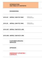
INTRODUCTION AND TABLE OF CONTENTS ENGINEERING DAIMLER, VOLVO, VOLKSWAGEN GROUP DAIMLER, VOLVO, VOLKSWAGEN GROUP 2016.208. AERIAL CAM ECO LINE CUSTOMER-SPECIFIC SERVICES APPENDIX EMERGENCY SITUATION / CONTACTS
Open the catalog to page 2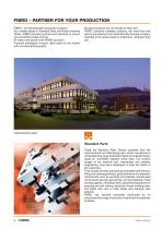
FIBRO – PARTNER FOR YOUR PRODUCTION FIBRO – an internationally successful company. As a market leader in Standard Parts and Rotary Indexing Tables, FIBRO provides products and solutions to ensure your production keeps moving. So what is the secret of the FIBRO success? Products developed in-house, tailor-made for the market with uncompromising quality. But good products are not enough on their own. FIBRO combines excellent products, the know-how and service competence of an internationally focused company, matched to the actual needs of customers - wherever they are. Hassmersheim plant Standard...
Open the catalog to page 3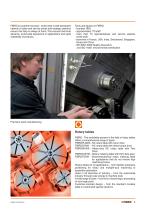
FIBRO is customer-focused – world-wide. A well-developed network of sales and service points and strategic partners ensure that help is always at hand. This ensures technical advance, world-wide experience in applications and rapid availability of products. Facts and figures on FIBRO: - founded 1958 - approximately 770 staff m - ore than 70 representatives and service stations world-wide b - ranches in France, USA, India, Switzerland, Singapore, Korea and China - ISO 9001:2000 Quality Assurance Precision parts manufacturing Rotary tables FIBRO - The worldwide pioneer in the field of rotary tables...
Open the catalog to page 4
IREPRESENTACIONES ■ PRZEDSTAWICIELSTWA ■ ZASTOUPENI ■ MUMESSILLER ■
Open the catalog to page 6
Experience and expertise you can rely on FIBRO Quality Assurance
Open the catalog to page 9
Experience and expertise you can rely on FIBRO Quality Assurance FIBRO is renowned for its quality world-wide. This high quality is achieved through our dedication and commitment to Quality Assurance. FIBRO testing starts on the raw material and continues right through production to the completed product. The test facilities themselves are also subject to stringent continuous testing. Only by setting itself such stringent standards can a company support its customers long term in safety, cost-effectiveness and quality. Tests during production Precision shape and contour testing equipment is used...
Open the catalog to page 10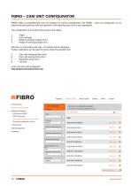
FIBRO offers a comprehensive cam unit portfolio for various requirements. The FIBRO - Cam unit configurator on our Internet site will assist you with the selection of the matching cam unit for your application. The configuration of your cam unit is done in four steps: 2. Cam unit type 3. Width of working surface (min.) 4. Height of working surface (min.) After this, an initial hitlist with max. 10 matches will be displayed. Further restrictions can be used to narrow down the selection list: 5. Cam unit working stroke (min.) 6. Cam unit working force (min.) Link to the cam unit configurator:...
Open the catalog to page 11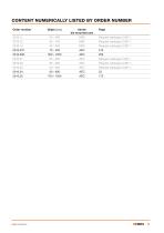
Order number Subject to alterations FIBRO 11
Open the catalog to page 12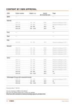
OEM Order number Width [mm] Aerial/ Page Volkswagen Group with corporate brands Processing status: 17.08.2016 Are you missing an OEM in this listing? Ask us for the latest release list or check our website http://www.fibro.de/de/normalien/produktgruppen/k-schieber.html. 12 ! FIBRO Subject to alterations
Open the catalog to page 13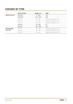
Order number Aerial cam unit 2016.207.
Open the catalog to page 14
14 ! FIBRO Subject to alterations
Open the catalog to page 15
INTRODUCTION AND TABLE OF CONTENTS DAIMLER, VOLVO, VOLKSWAGEN GROUP DAIMLER, VOLVO, VOLKSWAGEN GROUP CUSTOMER-SPECIFIC SERVICES EMERGENCY SITUATION / CONTACTS
Open the catalog to page 18
DESIGN, CONSTRUCTION
Open the catalog to page 19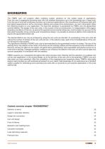
ENGINEERING The FIBRO cam unit program offers matching system solutions for the widest range of applications. From the use in progressive punching tools with the smallest dimensions up to the demanding use in large tools. From the use in tools with small piece numbers up to premium applications in the manufacture of bodywork parts with the highest requirements in terms of precision, lifetime and process force transmission, our cam unit program offers the matching solution to your application. The fault-free operation is guaranteed by FIBRO over the guaranteed, nominal lifetime. The design of...
Open the catalog to page 20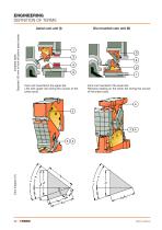
ENGINEERING DEFINITION OF TERMS Cam unit mounted in the upper die: Lifts with upper die during the course of the press cycle. Cam unit mounted in the lower die: Remains seating on the lower die during the course of the press cycle. Installed state, Depicted 100 mm in front of bottom dead center
Open the catalog to page 21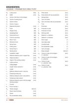
Cutting work Width Centre of the force of the stripper Centre of working force Centre of force Centre of mass n Diagonal dimension Force Stripper force Operating force Horizontal force n Force for punching Return force Retraction force Spring force Cutting force Vertical force n Working force Installation height Distance reference point / support top Height shoulder n Height of the working surface Cutting contour Cutting length Length contour element n Length Distance reference point / stop top Clamping surface top Distance reference point / stop bottom Clamping surface bottom Distance reference...
Open the catalog to page 23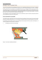
ENGINEERING DESIGN TOOL CONNECTION The size of the maximum force transferable by the cam unit is significantly influenced by the type of installation chosen. A technically correct selection of the installation type must be considered analogue to the cam unit design. The working force can be transmitted via the shoulder of the cam base on FIBRO cam units, alternatively via concealed fitting wedges on the cam base support. The shouldered installation allows maximum load values to be transferred, while a compact mounting space can be realized by installing via the concealed seating wedges. The reduced...
Open the catalog to page 24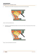
ENGINEERING DESIGN TOOL CONNECTION 2. Shouldering via cast shoulder in the upper area of the cam base, lower area exposed Figure 2: Cam base shouldered at top 3. Shouldering via inserted feather key between cam base and die casting in the upper area of the cam base, lower area exposed Figure 3: Cam base shouldered at top with key
Open the catalog to page 25
ENGINEERING DESIGN TOOL CONNECTION Force transmission via feather key In the case of lower requirements on the transmission of force, the cam unit can be installed in the tool by means of bracing via the key so that it is optimised to the installation space. For the mechanical machining of the feather key groove, in this case a distance from the groove geometry to the possible interference geometries in the die cast of at least 140 mm must be observed in order to avoid a collision of the milling spindle. Figure 4: Milling spindle clearance FIBRO cam units must be fitted with head cap screws having...
Open the catalog to page 26All FIBRO GmbH catalogs and technical brochures
 FIBRO STANDARD PARTS YOUR SYSTEM PARTNER
1364 Pages
 Flex Cam Unit
88 Pages
 RECIRCULATING BALL BUSHES
12 Pages
 THE CLEVER OPTION PILLAR CAM
2 Pages
 AERIAL CAM UNIT 2016.27.
38 Pages
 Standard parts
1355 Pages
 GROUND PRECISION COMPONENTS
247 Pages
 Guide Elements
330 Pages
 NUOVI PRODOTTI NELL´AREA CURSORI
197 Pages
 COMPOSITE PLATE SYSTEM
32 Pages
 Composite Plate System
32 Pages
 Catalog PDF (Peripherie)
63 Pages
 Catalog PDF (Elastomer)
33 Pages
 Catalog PDF (Fibrochemie)
21 Pages
 Standard Parts SYNOPSIS
32 Pages


Archived catalogs
 Projection Planning Manual
64 Pages
 In-Die Tapping Units (FTU)
12 Pages
 2490.14. Compact gas springs
6 Pages
 Spacer for die release
4 Pages
 BOLT LOCK SYSTEM
16 Pages
 ROTARY TABLES
7 Pages
 Spring Plungers
4 Pages
 Pneumatic transporters
4 Pages
 Electro-mechanical transporters
12 Pages
 Standard Parts SYNOPSIS
16 Pages


