- Catalogs
- FIBRO GmbH
- AERIAL CAM UNIT 2016.27.
- Company
- Products
- Catalogs
- News & Trends
- Exhibitions
AERIAL CAM UNIT 2016.27.
1 /38Pages

AERIAL CAM UNIT 2016.27.
1 /38Pages
Catalog excerpts

MEMBER OF THE LÄPPLE GROUP
Open the catalog to page 1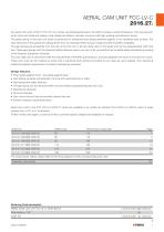
AERIAL CAM UNIT FCC-LV-C 2016.27. Our aerial cam units, 2016.27 FCC-OT-LV-C series, are distinguished due to its extrem compact overall dimensions. They are well suited for tools with small and medium-size strokes per lifetime, and also convince with high working and retraction forces. The glide pairing of this cam unit series is performed in sintered/bronze sliding elements against a non-hardened cast surface. The wear elements of the guides are catalog items from our Standard Parts product range and offer excellent availability. The gas springs are accessible from the rear of the cam unit in...
Open the catalog to page 2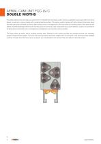
AERIAL CAM UNIT FCC-LV-C DOUBLE WIDTHS The width grading of the cam slide unit series 2016.27 is divided into 3x2 double widths, and thus available for each base width in a narrow design, as well as in a narrow design with a widened working surface. The narrow variants impress with their compact dimensions along the entire cam slide unit length, as well as high working forces on all segments of the cam slide unit working surface. With identical cam sliders, the widened designs offers more mounting space for low-force active components (e.g. punch retainers, scraper components) or for large active...
Open the catalog to page 3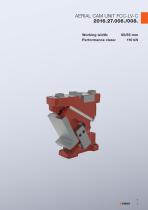
AERIAL CAM UNIT FCC-LV-C 2016.27.006./008. Working width: 65/85 mm Performance class: 110 kN
Open the catalog to page 4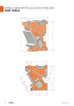
AERIAL CAM UNIT FCC-LV-C 2016.27.006./008. SIZE TABLE L
Open the catalog to page 5
AERIAL CAM UNIT FCC-LV-C 2016.27.006./008. SIZE TABLE Hexagon socket head cap screws DIN EN ISO 4762 / Strength class min. 8.8
Open the catalog to page 6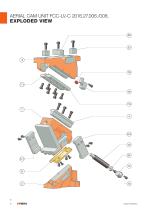
AERIAL CAM UNIT FCC-LV-C 2016.27.006./008. EXPLODED VIEW 20
Open the catalog to page 7
AERIAL CAM UNIT FCC-LV-C 2016.27.006./008. PARTS LIST Item No. Spare part Centre guide mechanical retraction, left 1.1191 with sinter layer mechanical retraction, right 1.1191 with sinter layer Sliding plate Bronze with solid lubricant L-guide, left 1.1191 with sinter layer L-guide, right 1.1191 with sinter layer Locking tappet Secure screw Slide stop Lockout system 22 23 24* (not shown) * not installed at all angles For inquiries or when ordering spare parts (x), we require the following data: ▬ Cam unit order no. ▬ Cam unit serial number ▬ Item No. / Designation / Spare part
Open the catalog to page 8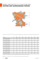
AERIAL CAM UNIT FCC-LV-C 2016.27.006./008. SYSTEM AND SURROUNDING FORCES All noted forces of 2016.27 FCC-OT-LV-C-series within this catalogue are pre-calculated values, calculated with higher margin of safety. α Order No * Retraction force values correspond to the spring-generated retraction force at the working point The forces F h2, Fv2 as well as F h3, Fv3 act on the tool environment at maximum working force
Open the catalog to page 9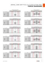
AERIAL CAM UNIT FCC-LV-C 2016.27.006./008. FORCE DIAGRAMS Support via cast shoulder Width 65/85 mm 22,5 20 22,5
Open the catalog to page 10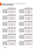
AERIAL CAM UNIT FCC-LV-C 2016.27.006./008. FORCE DIAGRAMS Support via cast shoulder Width 65/85 mm 22,5 20 22,5
Open the catalog to page 11
AERIAL CAM UNIT FCC-LV-C 2016.27.006./008. FORCE DIAGRAMS Support via cast shoulder Width 65/85 mm 22,5 20 22,5
Open the catalog to page 12
AERIAL CAM UNIT FCC-LV-C 2016.27.009./011. Working width: 90/115 mm Performance class: 180 kN
Open the catalog to page 14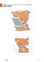
AERIAL CAM UNIT FCC-LV-C 2016.27.009./011. SIZE TABLE L
Open the catalog to page 15
AERIAL CAM UNIT FCC-LV-C 2016.27.009./011. SIZE TABLE Hexagon socket head cap screws DIN EN ISO 4762 / Strength class min. 8.8
Open the catalog to page 16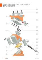
AERIAL CAM UNIT FCC-LV-C 2016.27.009./011. EXPLODED VIEW 20
Open the catalog to page 17
OAERIAL CAM UNIT FCC-LV-C 2016.27.009./011. PARTS LIST Item No. Spare part Centre guide mechanical retraction, left 1.1191 with sinter layer mechanical retraction, right 1.1191 with sinter layer Sliding plate Bronze with solid lubricant L-guide, left 1.1191 with sinter layer L-guide, right 1.1191 with sinter layer Locking tappet Secure screw Slide stop Lockout system 22 23 24* (not shown) * not installed at all angles For inquiries or when ordering spare parts (x), we require the following data: ▬ Cam unit order no. ▬ Cam unit serial number ▬ Item No. / Designation / Spare part
Open the catalog to page 18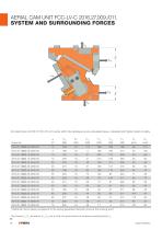
AERIAL CAM UNIT FCC-LV-C 2016.27.009./011. SYSTEM AND SURROUNDING FORCES All noted forces of 2016.27 FCC-OT-LV-C-series within this catalogue are pre-calculated values, calculated with higher margin of safety. α Order No * Retraction force values correspond to the spring-generated retraction force at the working point The forces F h2, Fv2 as well as F h3, Fv3 act on the tool envir
Open the catalog to page 19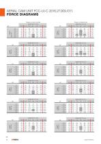
AERIAL CAM UNIT FCC-LV-C 2016.27.009./011. FORCE DIAGRAMS
Open the catalog to page 21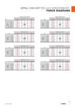
AERIAL CAM UNIT FCC-LV-C 2016.27.009./011. FORCE DIAGRAMS
Open the catalog to page 22
AERIAL CAM UNIT FCC-LV-C 2016.27.012./016. Working width: 125/160 mm Performance class: 250 kN
Open the catalog to page 24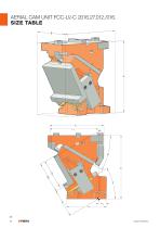
AERIAL CAM UNIT FCC-LV-C 2016.27.012./016. SIZE TABLE L
Open the catalog to page 25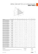
AERIAL CAM UNIT FCC-LV-C 2016.27.012./016. SIZE TABLE Hexagon socket head cap screws DIN EN ISO 4762 / Strength class min. 8.8
Open the catalog to page 26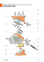
AERIAL CAM UNIT FCC-LV-C 2016.27.012./016. EXPLODED VIEW 20
Open the catalog to page 27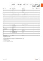
AERIAL CAM UNIT FCC-LV-C 2016.27.012./016. PARTS LIST Item No. Spare part Centre guide mechanical retraction, left 1.1191 with sinter layer mechanical retraction, right 1.1191 with sinter layer Sliding plate Bronze with solid lubricant L-guide, left 1.1191 with sinter layer L-guide, right 1.1191 with sinter layer Locking tappet Secure screw Slide stop Lockout system 22 23 24* (not shown) * not installed at all angles For inquiries or when ordering spare parts (x), we require the following data: ▬ Cam unit order no. ▬ Cam unit serial number ▬ Item No. / Designation / Spare part
Open the catalog to page 28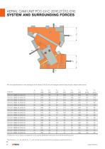
AERIAL CAM UNIT FCC-LV-C 2016.27.012./016. SYSTEM AND SURROUNDING FORCES All force specifications in this catalogue of the Series 2016.26 are pre-assigned values that provide a higher safety factor. α Order No * Retraction force values correspond to the spring-generated retraction force at the working point The forces F h2, Fv2 as well as F h3, Fv3 act on the tool envir
Open the catalog to page 29
AERIAL CAM UNIT FCC-LV-C 2016.27.012./016. FORCE DIAGRAMS
Open the catalog to page 30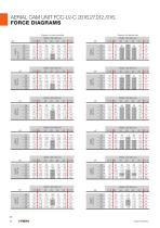
AERIAL CAM UNIT FCC-LV-C 2016.27.012./016. FORCE DIAGRAMS
Open the catalog to page 31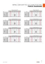
AERIAL CAM UNIT FCC-LV-C 2016.27.012./016. FORCE DIAGRAMS
Open the catalog to page 32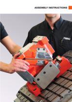
ASSEMBLY INSTRUCTIONS
Open the catalog to page 34
AERIAL CAM UNIT FCC-LV-C 2016.27. ASSEMBLY INSTRUCTIONS STEP 1 R emove secure screw (1). U nfasten locking screw (2) and re move gas spring (3) from the mount. Caution The gas spring may only be removed if the spring itself is released. After removing the locking screw for the gas spring, note that there is a risk of crushing between the cam slide unit body and the cam slide unit bed due to independent movement of the cam slide unit body. S lide the cam unit driver into the front position Caution Risk of crushing between the cam unit driver and the cam unit base by movement of the cam unit driver....
Open the catalog to page 35All FIBRO GmbH catalogs and technical brochures
 FIBRO STANDARD PARTS YOUR SYSTEM PARTNER
1364 Pages
 Flex Cam Unit
88 Pages
 RECIRCULATING BALL BUSHES
12 Pages
 THE CLEVER OPTION PILLAR CAM
2 Pages
 Standard parts
1355 Pages
 GROUND PRECISION COMPONENTS
247 Pages
 Guide Elements
330 Pages
 NUOVI PRODOTTI NELL´AREA CURSORI
197 Pages
 COMPOSITE PLATE SYSTEM
32 Pages
 Composite Plate System
32 Pages
 Catalog PDF (Peripherie)
63 Pages
 Catalog PDF (Elastomer)
33 Pages
 Catalog PDF (Fibrochemie)
21 Pages
 Standard Parts SYNOPSIS
32 Pages


Archived catalogs
 Projection Planning Manual
64 Pages
 In-Die Tapping Units (FTU)
12 Pages
 2490.14. Compact gas springs
6 Pages
 Spacer for die release
4 Pages
 BOLT LOCK SYSTEM
16 Pages
 ROTARY TABLES
7 Pages
 Spring Plungers
4 Pages
 Pneumatic transporters
4 Pages
 Electro-mechanical transporters
12 Pages
 Standard Parts SYNOPSIS
16 Pages


