- Catalogs
- Fibertex Nonwovens
- Design Guide Reinforcement
Design Guide Reinforcement
1 /20Pages

Design Guide Reinforcement
1 /20Pages
Catalog excerpts

Design Guide Fibertex Reinforcement
Open the catalog to page 1
Reinforcement Fibertex Reinforcement products are cost effective and offer considerable performance benefits in sub-base layers and in the construction of steep slopes. Fibertex Reinforcements are woven products made from various polymers including PP, PET and PVA (polypropylene, polyester, and polyvinyl alcohol). They are made from high tenacity yarns ensuring high strength and low elongation. For certain applications, Fibertex Reinforcements are coated with PVC for maximum durability. Focus on the environment No chemical binders are used in Fibertex products or during the production process....
Open the catalog to page 2
with Fibertex Reinforcement Steep reinforced slopes Reinforcing soils with high strength and low elongation geosynthetics enables soil structures to stay stable under high loads with vertical or near-vertical surfaces. The soils are added internal shear resistance through geosynthetics, and when wrapping the geosynthetics over the surface for each layer, the horizontal forces on the vertical surface are also absorbed in the geosynthetics. Asphalt reinforcement Reinforcing the lower part of the asphalt layer adds internal shear resistance to the asphalt. When the underlying surface contracts and...
Open the catalog to page 3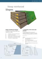
Steep reinforced Steep reinforced slopes The design of a steep reinforced slope can be divided into five stages: 1. 2. 3. 4. 5. Calculation of the total earth pressure Choice of reinforcement Determination of reinforcement spacing Determination of reinforcement length Calculation of wrapping length The vertical pressure from the soil and a possible surcharge, rv, is used later to calculate the necessary anchoring length and is found as: rv,z = q + c z • Where, rv,z vertical earth pressure at depth z in the the slope [kN/m2] q the surcharge load [kN/m2] c unit weight of the fill material [kN/...
Open the catalog to page 4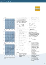
40° water • cwater H rh,z = K c z + K q ru =45° Soil Surcharge H • csoil • Where, rh,z lateral earth pressure the at depth z in the slope [kN/m2] lateral earth pressure the coefficient [can be read from figure 4] c unit weight of the the fill material [kN/m3] z vertical distance the from the top of the slope [m] q surcharge load the [kN/m2] u angle of internal the friction in the fill material [º] slope angle [º] Pore Water Pressure ru = Hwater • cwater H • csoil H Height of the slope[m] cw unit weight of the the water [kN/m3] csoil the unit weight of the soil [kN/m3] Figure: 3 Pore water pressure...
Open the catalog to page 5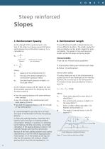
Steep reinforced Slopes 3. Reinforcement Spacing As the strength of the reinforcement in the face of the slope must always exceed the lateral earth pressure the reinforcement spacing, Sv, is calculated as: The reinforcement length is determined by one of two different situations. The length needed for internal stability and the length needed for external stability. The greater of two reinforcement lengths will be the design anchoring length. Tlt rh,z ≤ Sv Lateral earth Pressure Reinforcement strength per unit spacing Tlt Sv ≤ rh,z Where, Sv spacing of the reinforcement [m] Tlt long term tensile...
Open the catalog to page 6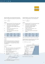
Required length of the reinforcement after failure plane for resisting direct sliding over reinforcement Required length of the reinforcement after failure plane for resisting pullout of the reinforcement Where, L,sliding Required length of the reinforcement after failure plane to resist direct sliding [m] Tlt long term tensile strength of a the reinforcement product [kN/m] (Found in section 2) B Width of the reinforcement in the anchorage zone [m] sds Shear stress required to resist direct sliding [kN/m2] Where, L,pullout Required length of the reinforcement after failure plane to resist pullout...
Open the catalog to page 7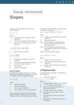
Steep reinforced Slopes Length of the reinforcement required for the internal stability L int ernal = L ε + L A Where, Linternal Total Reinforcement length for internal stability [m] L Reinforcement length after failure plane [m] LA Reinforcement length before the failure plane [m] angle of friction for design fm angle of internal friction in the fill the material [º] ƒm partial material coefficient (normally the set to1.4 for material security) Slope angle [º] H Height of the slope[m] External Stability For calculation of external stability the surcharge load if any is converted to an equivalent...
Open the catalog to page 8
Overall StabilityLength to height ratio to height ratioto height ratio External direct sliding Length to height ratio Length Length Length to height ratio Overall stability Overall stability Length to height ratio External directExternal direct sliding sliding Figure: 7 The Relation between the length of reinforcement and the slope height for the overall stability and external direct sliding at different pore water pressure [Jewel 1991]
Open the catalog to page 9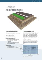
Asphalt reinforcement 1. Design of asphalt layer The design of reinforced asphalt pavements can be divided in to three parts: Asphalt reinforcement is used to prevent classical fatigue cracking of new asphalt or reflection cracking in asphalt repairs. The presence of the grid will inhibit cracking under repeated loading through control of local tensile strains and will therefore result in a lower required thickness of the layer. 1. Design of asphalt layer a. Design of layer thickness 2. Design of foundation layer a. Calculation of equivalent wheel load b. alculation of the pressure on C the fill...
Open the catalog to page 10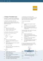
2. Design of foundation layer Foundation of a paved road can be designed as an unpaved road with small allowable rut depth. a. Calculation of equivalent wheel load Using the number of passes for the life of the paved structure, the equivalent wheel load is derived from the equation Where, Fe Equivalent wheel load [kN] Fp Maximum single wheel load [kN] Np Number of traffic passes [-] b. Calculation of the pressure on the fill layer The pressure on the fill layer is given by: Pf = Where, Pf Pressure on the fill layer [kN/m2] Fe Equivalent wheel load [kN] (calculated in section 2.a) Raf Radius of...
Open the catalog to page 11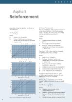
Reinforcement When Df/Raf is read the depth of the fill can be calculated from D D f = R af ∗ f R af Where, Df Depth of the fill layer [m] Raf Radius of distributed load between asphalt layer and fill layer [m] (calculated in section 2.b) f Design chart for (Cu/ f*Raf = 5) f Design chart for (Cu/ f*Raf = 10) f Design chart for (Cu/ f*Raf = 20) Figure: 3 Chart for designing the depth of the fill layer Where, Cu Undrained shear strength of subsoil [kN/m2] f Unit weight of fill material [kN/m3] Raf Radius of distributed load between asphalt layer and fill layer [m] (calculated in section 2.b) Where,...
Open the catalog to page 12All Fibertex Nonwovens catalogs and technical brochures
 F-300M for sound suppression
4 Pages
 Fibertex Weed Control Fabric
4 Pages
 Fibertex Quality Gardening
4 Pages
 Fibertex AM-2
8 Pages
 Civil Engineering
8 Pages
 Superior nonwovens inside
2 Pages
 Filtration
10 Pages
 Pre -preg and hand lay-up
2 Pages
 Nonwovens for blades
1 Page
 Vacuum Resin Infusion
2 Pages
 compoflex ® rF3
1 Page
 Needlepunch Spunbond
2 Pages
 Flooring brochure
4 Pages
 FiberAcoustic® brochure
2 Pages


Archived catalogs
 Efficient Filtration
2 Pages
 Compoflex®
2 Pages