- Company
- Products
- Catalogs
- News & Trends
- Exhibitions
Motor controller CMMO-ST
1 /13Pages

Motor controller CMMO-ST
1 /13Pages
Catalog excerpts

Motor controller CMMO-ST Worldwide: Superb: Easy: Festo core product range Covers 80% of your automation tasks q Generally ready for dispatch from the factory within 24 hours In stock at 13 Service Centres worldwide More than 2200 products Always in stock Festo quality at an attractive price Simplified procurement and warehousing w Generally ready for dispatch from the factory within 5 days Assembled for you at 4 Service Centres worldwide Up to 6 × 10¹² variants per product family Just look for the star!
Open the catalog to page 1
Motor controller CMMO-ST The motor controller CMMO-ST is an open- and closed-loop position controller Separate load and logic supply Supports the safe torque off (STO) safety function Easy to control via: – I/O interface – IO-Link or I-Port – Modbus TCP Communication system IO-Link • Monitoring of freely defined positions and torque ranges Backup file enables seamless device replacement • H-rail mounting possible • Encoder option (closed loop), in other words no step losses, following errors are corrected Parameterisation possible via: • Configuration package FCT (Festo Configuration Tool) •...
Open the catalog to page 2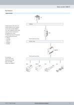
Motor controller CMMO-ST Key features System overview Fieldbus Fieldbus modules CTEU serve as an interface between the PLC controller and the motor controller CMMO-ST. This is then integrated into the control systems of various manufacturers using different bus nodes. The following protocols are supported using the appropriate module: • CANopen • DeviceNet • EtherCAT • PROFIBUS • PROFINET Point to point connection IO-Link / I-Port For controlling: Electric cylinder EPCO Toothed belt axis ELGR Rotary drive ERMO Stepper motor EMMS-ST Point to point connection d Internet: www.festo.com/catalogue/....
Open the catalog to page 3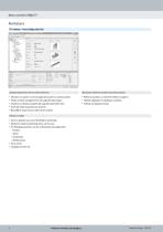
Motor controller CMMO-ST Key features FCT software – Festo Configuration Tool Software platform for electric drives from Festo • • • • • Mechanical reference positions and limit positions All drives in a system can be managed and saved in a common project Project and data management for all supported device types Simple to use thanks to graphically supported parameter entry Universal mode of operation for all drives Work offline at your desk or online at the machine • Reference positions can be either edited or taught in • Flexible adaptation to installation conditions • Settings are displayed...
Open the catalog to page 4
Motor controller CMMO-ST Nominal input voltage Motor controller Motor type Switching input/output Nominal current d Internet: www.festo.com/catalogue/...
Open the catalog to page 5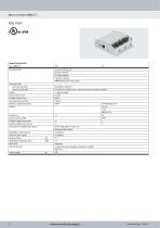
Motor controller CMMO-ST Data sheet General technical data Type CMMO-ST-... Operating mode Operating mode Open-loop operation Closed-loop operation Display Rotor position sensor Encoder interface input Parameterisation interface Ethernet, supported protocols Protocol Position sets Communication profile Number of digital logic inputs Number of digital logic outputs Characteristics of digital logic outputs Adjustable current reduction Nominal current setting Braking resistor Pulse power of braking resistor Mains filter Type of mounting Product weight Cascade controller with PI speed controller...
Open the catalog to page 6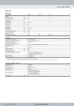
Motor controller CMMO-ST Data sheet Electrical data Type CMMO-ST-... General Max. DC link voltage Nominal output current Load voltage Nominal voltage Nominal current Peak current Logic supply Nominal voltage Nominal current Operating range of logic input Max. current per output (digital logic outputs) Switching logic, input/output Safety data Safety function to EN 61800-5-2 Performance level (PL) to EN ISO 13849-1 Safety Integrity Level (SIL) to EN 61800-5-2, EN 62061, EN 61508 Certificate issuing authority Proof test interval PFH Diagnostic coverage Safe failure fraction (SFF) Hardware fault...
Open the catalog to page 7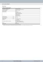
Motor controller CMMO-ST Data sheet Operating and environmental conditions Characteristics of digital logic outputs Characteristics of logic inputs Logic input specification Degree of protection Protective function Ambient temperature UL ambient temperature Storage temperature Relative humidity Certification CE marking (see declaration of conformity) KC mark Note on materials 1) Not galvanically isolated Galvanically connected to logic potential Based on IEC 61131-2 IP40 I²t monitoring Following error monitoring Software end-position detection Voltage failure detection Current monitoring Temperature...
Open the catalog to page 8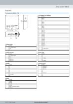
Motor controller CMMO-ST Data sheet Pin allocation for CMMO-ST-...-DIO [5] I/O interface, 25-pin Sub-D plug Pin Function [1] Reference switch Pin Function 1 2 3 +24 V (logic output) Signal 0 V Input 1 Input 2 Input 3 Input 4 Input 5 Input 6 Input 7 Input 8 Input 9 Input 10 Input 11 Output 1 Output 2 Output 3 Output 4 Output 5 Output 6 Output 7 Output 8 Output 9 Output 10 Output 11 n.c. +24 V (logic output) 0 V [2] Safety function STO Pin Function [6] Power supply Pin Function +24 V (logic output) STO 1 STO 2 Diagnostics 1 Diagnostics 2 [7] Ethernet interface Pin Function Tx+ (Transmit +) Tx–...
Open the catalog to page 9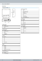
Motor controller CMMO-ST Data sheet Pin allocation for CMMO-ST-...-LK [5] I/O interface with IO-Link Pin Function 2 0 V 3 Parameterisable output 2 4 Parameterisable output 1 5 Ready/Error 6 Controller enable 7 n.c. 8 n.c. 9 L– (0 V IO-Link) 10 C/Q (IO-Link Signal) 11 L+ (+24 V supply to IO-Link) [6] Power supply Pin Function [1] Reference switch Pin Function 1 2 3 +24 V (logic output) Signal 0 V +24 V (logic output) STO 1 STO 2 Diagnostics 1 Diagnostics 2 Tx+ (Transmit +) Tx– (Transmit –) Rx+ (Receive +) n.c. n.c. Rx– (Receive –) n.c. n.c. String A String A/ String B String B/ Brake +24 V (switched...
Open the catalog to page 10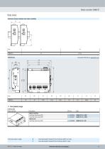
Motor controller CMMO-ST Data sheet Minimum distance between two motor controllers Download CAD data a www.festo.com w Core product range Ordering data Motor controller With I/O interface Switching input/output PNP Switching input/output NPN With IO-Link Switching input/output PNP Festo core product range Generally ready for dispatch from the factory within 24 hours Generally ready for dispatch from the factory within 5 days d Internet: www.festo.com/catalogu
Open the catalog to page 11All FESTO catalogs and technical brochures
 MCS®
MCS®52 Pages
 VZDB
VZDB12 Pages
 VLX
VLX6 Pages
 KVZA
KVZA10 Pages
 VZPR
VZPR38 Pages
 VZBM
VZBM39 Pages
 KVZB
KVZB10 Pages
 VZWP
VZWP8 Pages
 VYKB
VYKB14 Pages
 VYKA
VYKA14 Pages
 VZWM-L
9 Pages
 VZWF
VZWF12 Pages
 VZWD
VZWD19 Pages
 VZQA
VZQA19 Pages
 VZXF
VZXF34 Pages
 VZBF
VZBF26 Pages
 VZBD
VZBD57 Pages
 VZBC
VZBC57 Pages
 VZBA
VZBA57 Pages
 VAPB
VAPB57 Pages
 VZBE
VZBE42 Pages
 KDFP
KDFP3 Pages
 DFPD-HD
42 Pages
 DAPS
DAPS72 Pages
 DFPD
DFPD39 Pages
 DLP
DLP12 Pages
 VZXA
VZXA44 Pages
 DFPI
DFPI40 Pages
 DFPC
DFPC16 Pages
 CMSH
CMSH17 Pages
 CMSX
CMSX16 Pages
 DAPZ
DAPZ6 Pages
 SRAP
SRAP10 Pages
 SRBI
SRBI10 Pages
 SRBG
SRBG20 Pages
 SRBE
SRBE18 Pages
 SRBC
SRBC27 Pages
 VOFD
VOFD37 Pages
 VOFC
VOFC55 Pages
 VSNC-G1/8
19 Pages
 VSNC
VSNC92 Pages
 Sensor boxes SRAP, analogue
10 Pages
 Valve series VOFC
55 Pages
 Servo motors EMMB-AS
12 Pages
 Servo motors EMMT-AS
31 Pages
 VTSA-MP
2 Pages
 Proximity switches SDBT-MSB
6 Pages
 Filter regulators MS-LFR-B
11 Pages
 Pressure regulators MS-LR-B
11 Pages
 Silencers
17 Pages
 Electric cylinder units EPCS-BS
41 Pages
 Toothed belt axes ELGA-TB
110 Pages
 Spindle axes ELGC-BS-KF
27 Pages
 Angle seat valve VZXA
2 Pages
 Air/water valve VZWM
2 Pages
 Dispense head VTOI
2 Pages
 Motion Terminal VTEM
39 Pages
 Standard NAMUR valve VSNC
2 Pages
 Vacuum generators VN
2 Pages
 4/3 hand lever valve VHER
2 Pages
 Pressure sensor SPAN
2 Pages
 Food-safe tubing PUN-H-F
2 Pages
 Vacuum generator OVEL
2 Pages
 Stainless steel fitting NPQR
2 Pages
 Standard Fitting Series NPQE
2 Pages
 MS series service units
2 Pages
 Couplings - KD/KS
2 Pages
 Electric rotary drive ERMO
2 Pages
 Electric cylinder EPCO
2 Pages
 Electric cylinder EPCC
2 Pages
 Semi-rotary vane drive DRVS
2 Pages
 Angled gripper DHWC
2 Pages
 Radial gripper DHRC
2 Pages
 Long-stroke gripper DHPL
2 Pages
 Parallel gripper DHPC
2 Pages
 Twin cylinder DGTZ
2 Pages
 Mini slide DGST
2 Pages
 Pneumatic mini-slide DGSL
2 Pages
 Quarter turn actuator DFPD
2 Pages
 Linear actuator DFPC
2 Pages
 Guided drive DFM
2 Pages
 Compact cylinder ADN series
2 Pages


Archived catalogs

- FESTO valve
- Electromotor
- Piping
- Fitting
- FESTO manual valve
- FESTO control valve
- FESTO stainless steel valve
- FESTO water valve
- DC electromotor
- Screw-in fitting
- FESTO ball valve
- FESTO pneumatic valve
- Pneumatic fitting
- FESTO actuator
- FESTO solenoid valve
- Vacuum generator
- FESTO threaded valve
- Metal fitting
- Regulating valve