Catalog excerpts

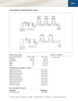
FEDERAL SIGNAL CORPORATION Synchronous Strobe Module Model SSM SYNCHRONIZE LOW IN-RUSH FEDERAL SIGNAL STROBES • Synchronizes strobe lights to 72 flashes per minute • Mounts on double-gang electrical box • UL1971 Approved for hearing impaired applications • Polarized design allows for remote supervision • Compatible with select Federal Signal model strobe lights (see chart) The Model SSM, Synchronous Strobe Module, is an electronic timing mechanism designed to energize select Federal Signal low in-rush 24VDC strobe lights simultaneously, while maintaining the ability to remotely supervise the strobe light circuit. This module is designed to synchronize a special series of Federal Signal strobe lights, which meet the requirement for Private-Mode Fire Alarm use, while maintaining the agency approval and environmental rating of the strobe light. The SSM is only compatible with Federal Signal brand strobe lights. See compatible models on the “How to Order” page. The SSM enables the customer to meet local building codes through a visually appealing “single-flash” created by the simultaneous control of strobe lights connected to it. Mixed signals are reduced to a minimum as reflection of many light pulses are now viewed as one single flash. The SSM mounts to the plaster ring of a double-gang electrical box, and requires 24 VDC at all times to operate the timing circuit. Screw terminals are provided for field termination of control wiring and a maximum of three non-Explosion-proof strobe lights or two Explosion-proof strobe lights may be connected to each SSM. Electrically, the SSM should be mounted in the middle of the circuit, with a maximum cable distance of 100’ from the SSM to each Strobe light. Supervision is accomplished the same as without the SSM, with a flash rate of 72 Flashes per minute in lieu of the advertised flash rate for each strobe light. The SSM is capable of switching 6 Amps of current. Please note: Not all strobe lights have the same in-rush current and therefore the SSM’s circuit’s switching potential may be reduced. Please see the application drawings on the second page. Model Operating Current Voltage SSM 0.95 amps 24VDC
Open the catalog to page 1
VISUAL SYNCHRONOUS STROBE MODULE (SSM) CONTROL PANEL OR POWER SUPPLY + + IN – 24VDC OUT + OUT +IN – OUT – IN – IN + OUT +IN – OUT – IN + OUT – OUT END OF LINE RESISTOR SYNC MODULE SSM 290A5130 FSEX–HI STROBE #1 + – 24VDC OUT +IN RED + 24VDC IN – FSEX–HI STROBE #2 BLACK– STROBE SIGNAL + – RED + + CONTROL PANEL OR POWER SUPPLY BLACK – RED + BLACK – RED + STROBE SIGNAL + 24VDC IN – FB24STHI OR 224XSTHI STROBE #3 +OUT –IN BLACK– – RED + + FB24STHI OR 224XSTHI STROBE #2 BLACK – FB24STHI OR 224XSTHI STROBE #1 + OUT +IN –OUT –IN –OUT END OF LINE RESISTOR SYNC MODULE SSM 2 S P E C I F I C AT I O N...
Open the catalog to page 2All FEDERAL SIGNAL catalogs and technical brochures
-
SPIRE® WORK ZONE DEFENSE
4 Pages
-
COM7 AND COM9 SCENE LIGHTS
2 Pages
-
Model G-MSC-2
4 Pages
-
Model G-STR
2 Pages
-
Model G-LED
2 Pages
-
Model 121SLED-N
2 Pages
-
Model 225XL-N
2 Pages
-
Litestak® Piezoelectric Horn
2 Pages
-
UniStat
2 Pages
-
StreamLine®
7 Pages
-
Certified Series
4 Pages
-
IP69K Products
8 Pages
-
MicroPulse® C Series
4 Pages
-
Commander® LC
2 Pages
-
Model DSA1
2 Pages
-
Informer-IP
2 Pages
-
TS100-N
2 Pages
-
Rumbler
2 Pages
-
MS4000 Series
2 Pages
-
PA300
2 Pages
-
DOT System Flasher
2 Pages
-
Perimeter Light Programmer
2 Pages
-
HRX Series Headache Rack
2 Pages
-
SW400
2 Pages
-
COMFL
2 Pages
-
Tractor and Utility Lights
2 Pages
-
2001-130 and Equinox Sirens
2 Pages
-
Radio Informer ANS347
2 Pages
-
VLBL Vehicular Light Bar
2 Pages
-
StreamLine Modular
8 Pages
-
SLM400/SLM450
2 Pages
-
350TR Vibratone® Horn
2 Pages
-
350 Vibratone® Horn
2 Pages
-
VALS Visalert® Strobe Light
2 Pages
-
LSB Litestak® Base
2 Pages
-
Fullline Brochure
8 Pages
-
LSS Litestak® Sound Module
2 Pages
-
LSL Litestak® Light Module
2 Pages
-
USI UniStat Status Indicator
2 Pages
Archived catalogs
-
Pure Brilliance Brochure
8 Pages
-
Systems Brochure
16 Pages
-
LED Brochure
2 Pages
-
ECHO Digital Intercom System
2 Pages
-
General Alarm Siren Model A
2 Pages
-
Vehicular Light Bar VLB
2 Pages
-
Full Line Brochure
2 Pages
-
Sleeker Package Brochure
8 Pages
-
Hazardous Area Brochure
8 Pages


