- Catalogs
- F.C.R. SPA
- UFO-C
UFO-C
1 /3Pages

UFO-C
1 /3Pages
Catalog excerpts
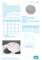
Disc circular diffuser UFO-C Description Disc diffuser for ceiling installation. The launch is horizontal radial with Coanda effect, through the circular slot that is created between the body of the diffuser and the disc : the distance between these two is variable on three positions. Inside a intermediate height adjustable disc (screw adjustment) acts as a damper. Characterized by a simple and elegant design, it is tipically used in civil environments for office conditioning, shops, hospital structures snd exibition spaces. Construction painted Natural aluminum (body), painted galvanized steel (disc). Finish White RAL 9010 gloss, powder-coated polyester type. Xn2 isothermal horizontal throw (isotachia 0.2 m / s) Lwa sound power level (rif. 10-12 W) Accessories PLSC : Standard plenum with lateral inlet. PLIC : insulated* plenum with lateral inlet. * polyurethane internal isolation thickness. 6 mm, cl.1 Specifications Adjustable disc circular diffuser for ceiling installation. Radial horizontal launch. Steel and aluminum painted white RAL 9010. F.C.R. SpA - Via E. Fermi, 3 - 20092 Cinisello Balsamo (MI) - Italy phone +39 02 61798 1 - fax +39 02 61798 300 - www.fcr.it - [email protected]
Open the catalog to page 1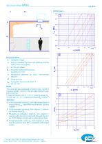
Disc circular diffuser distance between the center of the diffuser and the wall to which the jet flows X0,2 horizontal isothermal free throw (isotachìa 0,2 m/s) Dt DP installation height temperature difference (air input - environment setpoint) Pressure drop LWA A-weighted sound power level “A” (rif. 10-12 W) The value of d was calculated in relation to X0,2 and hi to maintain residual velocity in the occupied area within the limit of 0,2 m/s In case of diffusion with Dt = -10 °C (cooling) reduce X0,2 of 15%, with Dt = 10 °C (heating) increase X0,2 of 20%. 1 At the requested volume qv, with the...
Open the catalog to page 2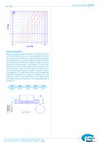
Disc circular diffuser Airflow calculation Because of the possible asymmetry caused by the plenum and the flexible duct, you should position the probe for measuring the speed of vk in at least 4 points equally spaced angularly. You must employ hot-wire anemometers, taking care to orient the “window” radially. You must place the probe as shown: in the middle of the slot near the same (in the first few inches from the exhaust velocity is constant - zone 1). At each point you have to measure the average speed in a range of at least 1 minute (average time). To obtain the air flow, then calculated...
Open the catalog to page 3All F.C.R. SPA catalogs and technical brochures
 FCROLL
1 Page
 UNI-BOX
1 Page
 MULTI-PAK 3V
2 Pages
 TRZT
TRZT1 Page
 LF
LF7 Pages
 LC
LC10 Pages
 DMAN
DMAN3 Pages
 T-SPOT
5 Pages
 UFO-EH
4 Pages
 LD / LD-Q
7 Pages
 DMF
DMF3 Pages
 UFO-EHC
3 Pages
 UFO-N
UFO-N3 Pages
 CIRCLE LINE
3 Pages
 DRA
DRA3 Pages
 DKE
DKE3 Pages
 BPA 20
5 Pages
 BPA 20 Box
3 Pages
 BZC
BZC4 Pages
 LPB 10
4 Pages
 DES
DES3 Pages
 MQZ
MQZ1 Page
 MCZ
MCZ1 Page
 KCA
KCA1 Page
 FCA
FCA1 Page
 CPT
CPT1 Page
 MMX
MMX1 Page
 GLC
GLC1 Page
 GLZ
GLZ1 Page
 WLZ
WLZ1 Page
 MTS-8
MTS-81 Page
 MTS-9
MTS-91 Page
 MAT-FLO
1 Page
 MAT-GLAS
1 Page
 BNT
BNT1 Page
 CFX/CFE/CFA/CFD
2 Pages
 PCA-1/PCE-1/PCG-1
1 Page
- Radial fan
- Propeller fan
- Air circulation fan
- Filter cartridge
- Extraction fan
- Industrial use filter
- Pressure separator filter
- Industrial filter cartridge
- Fine filter cartridge
- Panel filter
- General purpose filter cartridge
- Filter element
- Automatic filter
- Air filter cartridge
- Steel filter
- Wall-mounted fan
- Bag filter
- Filter bag
- Air duct
- Galvanised steel fan