Mezzanine High-Speed High-Density Connectors

Mezzanine High-Speed High-Density Connectors
The document outlines the technical specifications and performance data for FCI's MEG-Array® and GIG-Array® connectors, which are designed for high-speed, high-density applications in communication systems.
This section explains key terms such as reference planes, risetime conventions, and connector impedance. It also covers the mezzanine link build-up and PCB parameters.
A summary table compares the electrical performance of MEG-Array® and GIG-Array® connectors across different stack heights, indicating their suitability for various applications.
Details the MEG-Array® connectors, which support 10Gb/s applications with up to 528 signal pins. Features include RoHS compliance, BGA termination, and stack heights from 4mm to 14mm. They offer less than 1% crosstalk in differential configurations and meet Telcordia and NPS specifications.
The GIG-Array® connectors are designed for applications with up to 296 signal pins and support stack heights from 15mm to 40mm, optimized for high-speed differential applications.
Provides dimensional outlines and part number selectors for both connector systems, aiding in the selection of appropriate connectors based on application needs.
Includes links to additional technical documents and resources for further information on the connector systems.
The document serves as a comprehensive guide for selecting optimal FCI mezzanine connectors, ensuring high performance and reliability in communication and data systems.
Propagation Delay: Measured at 50% of input amplitude, delays for stack heights of 4mm, 10mm, and 14mm are 24.21 ps, 54.33 ps, and 70.50 ps, respectively.
Crosstalk: Near-end crosstalk is significant, while forward crosstalk is negligible. Multi-pair active crosstalk is the worst-case scenario.
Eye Diagrams: Eye patterns for stack heights are shown with specific test conditions.
Introduction: Covers differential electrical performance data for stack heights of 15mm to 35mm.
Connector Performance Configuration: Includes dedicated ground rows and columns with differential pairs in signal rows.
Differential Impedance: Impedance varies slightly with risetime and stack height.
Differential Attenuation: Attenuation data for differential pairs is provided.
Propagation Delay: Delays range from 53.23ps to 132.45ps for stack heights from 15mm to 35mm.
Crosstalk: Near-end multi-pair active crosstalk is the worst-case scenario.
Eye Diagrams: Eye patterns for stack heights are shown with similar test conditions as the MEG-ARRAY® system.
Catalog excerpts

COMMUNICATIONS, DATA, CONSUMER DIVISION GIG-ARRAY > and MEG-ARRAY > ή Electrical Performance Data >
Open the catalog to page 1
With operations in 30 countries, FCI is a leading manufacturer of connectors. Our 13,500 employees are committed to providing customers with high-quality, innovative products for awide range of consumer andindustrial applications. 2 >
Open the catalog to page 2
Todays communication technology requires the transmission of increasingly higher data rates, driving the need for enhanced hardware to preserve signal integrity in these systems. The system designer is challenged to maximize system performance by balancing three interacting components to maximize system performance: ҕ Integrated circuit chips Multi-layer boards Օ Interconnect systemsFCI recognizes that the interconnection of complex subsystems is a crucial factor in the design of data and communications equipment. To meet evolving high-speed performance requirements, we have developed a comprehensive...
Open the catalog to page 4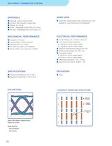
Housing: Liquid Crystal PolymerContact: High Strength Copper Alloy Plating: Au over Ni SnPb Ζ Solderballs: 63Sn/37Pb 0.76mm Pb-Free ؖ Solderballs: 95.5 Sn/4 Ag/0.5 Cu Spice files, signal integrity data, drawings and moreavailable at: www.fciconnect.com/highspeed > Durability: 25 Cycles Contact Wipe: 2.00mm Nominal Telcordia GR-1217-CORE IPC-SM-785 Solder Joint ReliabilityPassed 6000 cycle solder joint reliability Current Rating: 1A / Contact <30C ТȆ TLow Level Contact Resistance:<20m բĦ for 15mm mated height<32m բĦ for 35mm mated heightDielectric Withstanding Voltage=500 VAC Withstanding Voltage=167...
Open the catalog to page 10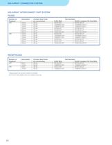
GIG-ARRAY > CONNECTOR SYSTEM GIG-ARRAY > ή INTERCONNECT PART SYSTEM PLUGS RECEPTACLES > Number of DescriptionContact Area Finish Part NumbersPositions*(in microinches)SnPb BGARoHS Compliant Pb-Free BGA 20010mm 30 Au55737-00155737-001LF12mm30 Au10026802-00110026802-001LF 13mm30 Au10060910-00110060910-001LF 15mm30 Au55738-00155738-001LF 20mm30 Au55739-00155739-001LF 25mm30 Au10054783-00110054783-001LF29610mm 30 Au55720-00155720-001LF12mm30 Au10026804-00110026804-001LF 13mm30 Au10060911-00110060911-001LF 15mm30 Au55700-00155700-001LF 20mm30 Au55727-00155727-001LF 25mm30 Au10054784-00110054784-001LF...
Open the catalog to page 12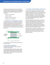
This manual describes the high-speed electrical performanceofthe MEG-Array > and GIG-Array > ή connectors. Throughout thedocument, a number of assumptions and conventions are used. This introduction summarizes the following conventions and assumptions:Definition of reference planes ՕRisetime convention Definition of connector impedance ՕDescription of the mezzanine link The term connector impedance can have different meanings. Itis quite common to grossly simplify the connector and state that it has an impedance of xӔ ohms. This can mean the average impedance of the connector, as measured using...
Open the catalog to page 14
Figure 1-2 shows calibration traces that are equivalent to 2 timesthe length of any trace in the connector measurement area. By shorting the input SMA you are able to locate the beginning of the SMA / Board transition as shown in Figure 1-3. The figure defines this point to be at 5.05ns. If you perform the same procedure on the output SMA you will be able to locate the end of the SMA / Board transition as shown in Figure 1-4. The short on the output islocated at 5.15ns. The measurement details the discontinuity caused by the viatransition where the connector attaches. It is easy to find the discontinuity...
Open the catalog to page 15
The mezzanine link used in testing is shown in Figure 1-6. Anumber of channels on the header side are connected to a number of channels on the receptacle side. All connections are point to point, and signals propagate from the header board to the receptacle board. An eye pattern is a good indication of the receivers ability tointerpret signals correctly. It includes the effects of link loss, ISI (intersymbol interference), transmitter jitter, and system noise.To quantify the eye opening, we will use a performance maskbased on the following two performance metrics (Figure 1-7)ҕNormalized maximum...
Open the catalog to page 16
Product TypeDifferentialDifferential***10 Gb/s**PropagationMultiactiveDifferential and Stack HeightImpedanceInsertionEyeDelayNEXTPairs Per Tr = 100pSLoss (S21)Tr = 100pSLinear inch 4mm MEG-Array > 91.0 / 100.05.32 GHzPass24.21ps<1%39 10mm MEG-Array > ή 100.0 / 104.05.30 GHzPass54.33ps<1%39 14mm MEG-Array > 100.0 / 112.05.65 GHzPass70.50ps<1%39 15mm GIG-Array > ή 96.48 / 99.746.85 GHzPass53.23ps<1.24%51* 20mm GIG-Array > 93.5 / 102.65.12 GHzPass87.57ps<1.13%51* 25mm GIG-Array > ή 93.0 / 107.44.25 GHzPass108.19ps<1.14%51* 30mm GIG-Array > 96.50 / 108.326.50 GHzPass117.52ps<1.25%51*35mm GIG-Array...
Open the catalog to page 17
3.4 DIFFERENTIAL ATTENUATION > The attenuation of differential pair S7 and S8 (from Figure 3-1)for each stack height is shown in Figures 3-27 thru 3-29. Figure 3-27 Differential Attenuation of 4mm stack height Figure 3-28 Differential Attenuation of 10mmstack height Figure3-29 Differential Attenuation of 14mmstack height 22 >
Open the catalog to page 22
The propagation delay is the time needed for a signal topropagate through a connector pair. It is calculated as the difference in time between the transmitted signal and input signal at a signal level equal to 50% of the input amplitude. Figures 3-30 thru 3-32 summarize the data for the 4,10 and 14mm stack heights. > Figure 3-31 10mm stack height Delay Figure3-30 4mm stack height Delay Figure3-32 14mm stack height Delay >
Open the catalog to page 23
Single-pair active crosstalk is the crosstalk measured at onepair when a signal is injected onto a second pair. The backward or near-end crosstalk is the crosstalk measured at the same end as the injected signal. The forward or far-end crosstalk is measured at the end opposite the injected signal. The forward crosstalk is so small in the mezzanine connectors that the values are negligible. Likewise, the single active horizontal and diagonal coupling is also negligible. Therefore, only the near-end multi-pair active crosstalk is presented.Themulti-pair active crosstalk is the maximum crosstalk...
Open the catalog to page 24All FCI catalogs and technical brochures
 Conan® Lite 1.00mm Connector
3 Pages
 ExaMAX2®
2 Pages
 Passive Fiber Optic Systems
8 Pages
 BERGSTAK ®
4 Pages
 Minitek Pwr 4.2
2 Pages
 PWRMAX
2 Pages
 PwrBlade+
2 Pages
 PwrLoPro
2 Pages
 FCI Lighting Applications
8 Pages
 FCI Power Solutions
12 Pages
 AirMax® High Speed Family
5 Pages
 examax
13 Pages
 Mini-SAS HD product
17 Pages
 10GB ETHERNET SFP+
2 Pages
 Connector Overview
100 Pages
 GIG-Array
4 Pages
 D-Sub Overview
2 Pages
 Meg-Array
6 Pages
 Conan-I Series
2 Pages
 AirMax VS® Cable Assembly
2 Pages
 QSFP Copper Cable Assemblies
4 Pages
 Minitek Active Latch Housing
4 Pages
 Power Solutions
38 Pages
 Minitek127® Catalog
44 Pages
 1.25mm Wire-To-Board System
2 Pages
 Micro USB Datasheet
2 Pages
 120Gbit/s CXP-CXP AOC
2 Pages
 Safety Restraint Solutions
7 Pages
 Storage Interface Brochure
20 Pages
 Terminal Blocks Catalog
20 Pages
 LED Brochure
4 Pages
 Power Distribution Solutions
2 Pages
 DIN 41612
16 Pages


Archived catalogs


- Data connector
- Electrical power supply connector
- Metal connector
- Polymer connector
- Socket electrical connector
- Screw-in connector
- Industrial connector
- Junction block
- Rectangular connector
- Flexible cable
- Straight connector
- Cable connector
- Optical cable
- Copper connector
- Screw connection terminal block
- Cable assembly
- DIN connector
- Plug-in connector
- Crimp connector