
- Catalogs
- FAULHABER Drive Systems
- Encoders - Series IEX3- L


Encoders - Series IEX3- L
Encoders - Series IEX3- L
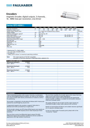
- Lines per Revolution: Options range from 16 to 4096 lines.
- Frequency Range: Up to 875 kHz depending on the model.
- Supply Voltage: 4.5 to 5.5 V.
- Current Consumption: Typical 25 mA, maximum 40 mA.
- Operating Temperature: -40 to +100 °C.
- Accuracy: Typical 0.5 °m with repeatability of 0.08 °m.
- Mean Time to Failure (MTTF): 4,002,000 hours.
- The encoders provide three output channels and are integrated into the Brushless DC-Motors BXT H-Series, extending the motor length by 6.2 mm.
- They feature a segmented magnetic disc and an angle sensor to process the magnetic field.
- Output signals include two 90° phase-shifted square wave signals and an index impulse per motor revolution.
- The Line Driver version offers differential signal outputs (TIA-422) to reduce ambient interference, suitable for long cable applications.
- Encoders are compatible with Brushless DC-Flat Motors series BXT H.
- Connection is facilitated through a PVC ribbon cable with connector variants compliant with EN 60603-13 / DIN-41651 standards.
- Incorrect lead connection can damage motor electronics.
- Three dimensional drawings (A, B, C) are provided for different motor combinations (2214, 3216, 4221).
- For detailed technical data and lifetime performance, refer to the “Technical Information” section.
- Specifications are subject to change without notice.
Catalog excerpts
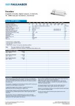
FAULHABER Encoders magnetic Encoder, digital outputs, 3 channels, 16 - 4096 lines per revolution, Line Driver Lines per revolution Frequency range, up to1) Signal output, square wave Supply voltage Current consumption, typical2) Index Pulse width3) Phase shift, channel A to B Inertia of sensor magnet Operating temperature range Accuracy, typ. Hysteresis Edge spacing, min. 2+1 Index and complementary outputs 2) Udd= 5 V: with unloaded outputs 4) „Mean time to failure" at maximum operating condition Note: The output signals are TIA-422 compatible. Examples of Line Driver Receivers: ST26C32AB (STM), AM26C32 (TI). These incremental encoders with 3 output channels, in combination with the FAULHABER Brushless DC-Motors, are used for the indication and control of both shaft velocity and direction of rotation as well as for positioning. The encoder is integrated in the Brushless DC-Motors BXT H-Series and extends the overall length by only 6,2 mm. A segmented magnetic disc provides a magnetic field which is detected and further processed by an angle sensor. At the encoder outputs, two 90° phase-shifted square wave signals are available with up to 4096 impulses and an index impulse per motor revolution. The Line Driver amplifies the encoder signal which means that long cables can be used without signal degradation. Differential signal outputs must be decoded by the appropriate receiver module. In addition, a suitable line termination resistance (100 ohm) is possibly useful. The supply voltage for the encoder and the output signals are interfaced through a ribbon cable, optional with connector. Details for the Brushless DC-Motors and suitable reduction gearheads are on separate catalogue pages. To view our large range of accessory parts, please refer to the "Accessories" chapter. For combination with Motor The Line Driver version has differential signal outputs (TIA-422). Differential signals reduce ambient interference and are suitable for applications with high ambient ii © DR. FRITZ FAULHABER GMBH & CO. KG Specifications subject to change without notice. For notes on technical data and lifetime performance refer to “Technical Information".
Open the catalog to page 1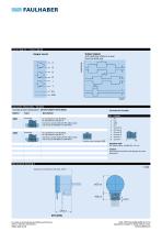
FAULHABER Circuit diagram / Output signals Output circuit A Output signalswith clockwise rotation as seen from the shaft end Angle Connector information / Variants Standard cable Incorrect lead connection will damage the motor electronics! Example of combination with 2214...BXTH - L1 ±0,3IEF3-4096L © DR. FRITZ FAULHABER GMBH & CO. KG Specifications subject to change without notice. For notes on technical data and lifetime performance refer to “Technical Information". for combination with Brushless DC-Flat Motors series BXT H. Connector variants AWG 28 / PVC ribbon cable with connector EN 60603-13...
Open the catalog to page 2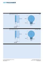
Dimensional drawing B Example of combination with 3216...BXTH L1 ±0,3 IEF3-4096L Dimensional drawing C Scale reduced Example of combination with 4221...BXTH For notes on technical data and lifetime performance refer to “Technical Information”. Edition 2026 Jul. 28 © DR. FRITZ FAULHABER GMBH & CO. KG Specifications subject to change without notice. www.faul
Open the catalog to page 3All FAULHABER Drive Systems catalogs and technical brochures
 FAULHABER nmotion 1/2026
48 Pages
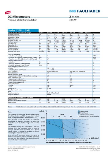 Series 1218 ... SXR
2 Pages
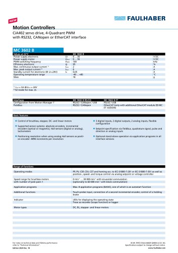 MC 3602 B
2 Pages
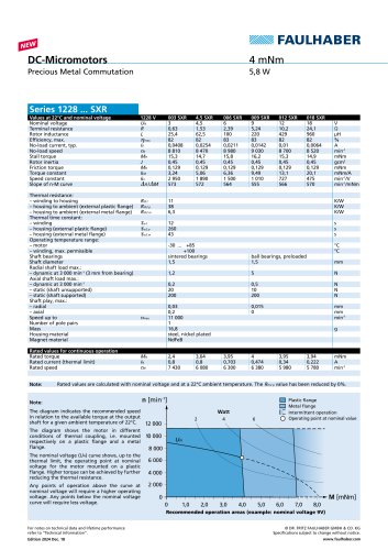 Series 1228 ... SXR
2 Pages
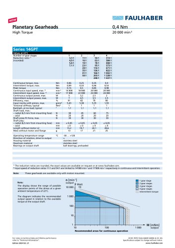 14GPT
2 Pages
 FAULHABER motio
36 Pages
 FAULHABER motion 1/2023
32 Pages
 Motion Controllers MC 3603 S
2 Pages
 FAULHABER motion 1/2021
24 Pages
 FAULHABER motion 2/2022
24 Pages
 Linear Actuators L series
12 Pages
 FAULHABER motion 1/2022
33 Pages
 Faulhaber motion 02/2021
28 Pages
 The magazine with drive
28 Pages
 motion 1/2020
32 Pages
 Technical Information
162 Pages
 motion 2/2019
28 Pages
 FAULHABER motion 2/2017
28 Pages
 FAULHABER motion 1/2017
28 Pages
 motion the magazine with drive
28 Pages
 Drives Systems
40 Pages
 motion the magazine with drive
28 Pages
 The magazine with drive
28 Pages
 EVOLUTION humanoids ROBOTICS
28 Pages
 TECHNOLOGY UNDER THE SKIN
24 Pages


Archived catalogs
 FAULHABER motion 2025
36 Pages
 The magazin with drive 1/2019
28 Pages
 Drive Systems
521 Pages
 FAULHABER Info Issue 1/2013
16 Pages
 news brochure
48 Pages
 FAULHABER info issue 1 / 2012
20 Pages
 FAuLHABER info issue 2 / 2011
16 Pages
 FAULHABER info edition 1/2011
16 Pages


- FAULHABER electric motor
- FAULHABER DC motor
- FAULHABER synchronous motor
- Actuator
- Alternating current motor
- Multipole motor
- Electric gearmotor
- FAULHABER rotary encoder
- Linear actuator
- FAULHABER planetary gear reducer
- FAULHABER coaxial gear reducer
- Electric actuator
- Electromotor for industrial applications
- EC motor
- Precision gearhead
- 24 V motor
- FAULHABER servomotor
- Incremental rotary encoder
- Direct current gear-motor