

Air-Oil Lubricator unit - LTO.01
Air-Oil Lubricator unit - LTO.01
Catalog excerpts
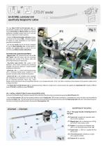
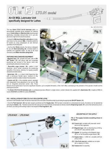
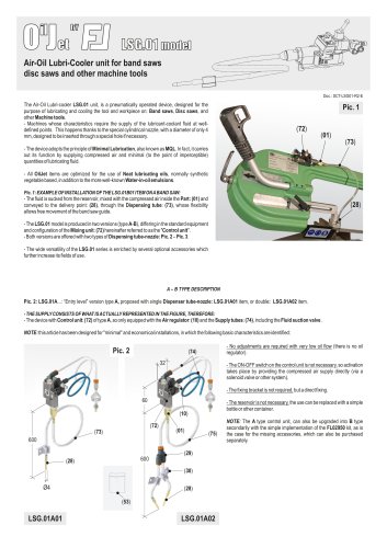
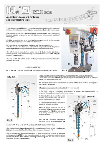
LTO.01 model Air-Oil MQL Lubricator Unit specifically designed for Lathes Doc.: SCT-LTO.01-R1-E The new OilJet LTO.01 Air-Oil lubricator unit, is a pneumatically operated device designed for intensive use on Centre lathes and Machine tools requiring rapid positioning, immediate removal when not in use and, above all, a high level of overall robustness. - It adopts the Minimum Quantity Lubrication principle, also known by the acronym MQL, it therefore performs its function by using compressed air and minimum quantities of lubricating fluid. - Like the other OilJet products, the device is designed for use with Neat lubricating oils, normally based on synthetic and vegetable esters, as well as the most commonly used Water-miscible cutting fluids. FEATURES AND STANDARD EQUIPMENT: - Magnetic base: (37), powerful and solid, with an ONOFF Switch: (51) that allows safe and immediate positioning and removal of the device, while also preventing the attraction of nearby chips. - Reversible angle bracket: (38), usable in both directions, which further enhances the positioning versatility of the device, allowing it to bypass possible obstacles and obstructions. - Spiral-tube: (39), i.e. a robust metal dispensing tube with a continuous flexible spiral, resistant to chip projection and able to stably maintain the set position. - Control unit (52), in the complete version, equipped with independent micro-adjustment of air and oil: (54) and an integrated pneumatic switch: (12). These features ensure great ease of use and a significant reduction, up to complete elimination, of the “mist” effect, contributing to the protection of the operator’s health and the working environment. - The OilJet LTO.01 Air-Oil lubricator unit, is a professional product offered in a single version, (variant indicator: A), supplied with a Spiral-tube (39) in lengths of 310 mm (code: LTO.01A31) and 410 mm (code: LTO.01A41). FIG. 1: INSTALLATION OF ITEM LTO.01A31 ON A CENTRE LATHE: As shown in the illustration itself, the device is secured to the cross slide of the lathe simply by activating the appropriate ON-OFF Switch: (51). - Once the Fluid reservoir: (22) has been properly positioned and the Supply tube: (13) has been connected to a compressed-air source, the device can be operated by activating the Switch: (12). The fluid is drawn from the reservoir and mixed with the compressed air directly inside the Dispensing nozzle: (01), and is then delivered as an airoil mixture, according to the settings made on the respective Flow regulators: (54). DESCRIPTION OF THE SUPPLY: FIG. 2: The supply includes everything shown in the figure: (13) - (52) Control unit: complete with pneumatic switch and air-oil flow regulators. - (37) Magnetic base: with an attracting force of 80 kg and ON-OFF rotary selector switch. - (53) Adapter: for mounting on the Magnetic base: (37) or on the Reversible angle bracket: (38). - (13) Supply tubes: L = 2000 mm, complete with fluid pick-up valve. - (22) 1-litre fluid reservoir: available as an option with a capacity of 2-litres.
Open the catalog to page 1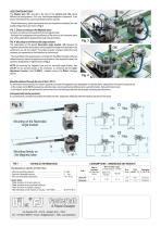
USE CONFIGURATIONS: The Adapter part: (53), secured to the base of the Control unit: (52), allows different use configurations. As it is an "intermediate adaptation component”, it can also be manufactured to custom specifications when required. - Overall dimensions, space requirements and any comparisons between the main usable configurations are shown in Fig. 5. FIG. 3: Direct mounting on the Magnetic base: As shown, the device is secured directly to the magnetic base. - Although this arrangement limits positioning of the device to the horizontal plane only, where applicable it represents the...
Open the catalog to page 2All Fasterlab catalogs and technical brochures
 Taping Machine BLA10
2 Pages
 Taping Machine BLA01
2 Pages
- Greasing system
- Oil greasing system
- Pneumatic greasing system
- Automated lubrication system
- Minimal quantity lubrication unit
- Taping machine
- Machine tool lubrication unit
- Spray lubrication unit
- Air/oil lubrication unit
- Adhesive tape taping machine
- Progressive greasing system
- Single-line lubrication unit
- Milling lubrication system
- Machining center lubrication unit
- Manual setting taping machine
- Spindle lubrication unit
- Dual line greasing system
- Automatic taping machine
- Drilling machine lubrication unit
- Metal machining lubrication unit