
- Catalogs
- Farris Engineering
- Serie 2700

Serie 2700

Serie 2700
The document provides comprehensive details on the Series 2700 Pressure Relief Valves, designed for the process industry with various sizes, orifices, and materials. These valves are suitable for air, steam, vapor, and liquid services, emphasizing part interchangeability for maintenance and cost efficiency.
The Series 2700 valves comply with the ASME Boiler and Pressure Vessel Code, Section VIII, with capacities certified by The National Board of Boiler and Pressure Vessel Inspectors. They feature a fixed blowdown design, built-in lift stop, and balanced design to counteract back pressure effects.
The ordering system is detailed, with each digit representing attributes like series number, orifice area, seat construction, and material variations. Customers should specify quantities, sizes, type numbers, connections, materials, set pressures, and operational parameters for accurate processing.
Materials for conventional and balanced designs are listed, including standard stainless steel and carbon steel, with optional Monel and Hastelloy for specific applications.
Selection tables for conventional and balanced designs are provided in U.S. customary and metric units, detailing threaded and flanged connections, orifice areas, valve sizes, type numbers, maximum set pressures, and material specifications.
Capacity tables for air, steam, and water are included, detailing specifications for different units and conditions.
An optional O-ring seat design is available for maximum seat tightness, with Teflon options for higher pressures. Pressure and temperature limits for elastomer and Teflon seats are provided.
Dimensions and weights for the valves are provided to ensure proper selection and installation.
Farris Engineering offers a warranty against defects in material and workmanship, with conditions for returns and replacements outlined.
The Series 2700 Pressure Relief Valves provide a reliable and versatile solution for industrial applications, focusing on compliance with industry standards.
The document outlines specifications for various valve series, including ASME certification, size range, pressure and temperature limits, materials, and options.
Farris Engineering's products are certified under standards like ASME, National Board, ISO 9001-2000, and others, with global approvals such as PED, ATEX, and Canadian TSSA Registration.
Farris Engineering offers a global network of service centers with factory-trained technicians, providing local inventory and 24/7 valve service and replacement.
- Global Exchange Program: Access to Farris inventory through a web-based platform.
- Certifications: ASME/VR certified assembly and test facilities.
- Support Services: Application, sizing, and selection support for pressure relief systems.
- Engineering Services: Includes pressure relief system audits, design services, and support for process safety management (PSM) requirements.
- Software Tools: iPRSM® engineering software for PSM calculation and documentation, and SizeMaster™ Mark IV for pressure relief valve sizing and selection.
- Product Specifications: Various series of pressure relief valves certified for air, steam, and water, including Series 2600, 3800, 2700, 1890/1896M, and 2850/2856. Steam safety valves include Series 4200 and 6400/6600, certified for Steam – Section I & VIII.
The document emphasizes the importance of certifications and software tools in ensuring the safety and efficiency of pressure relief systems.
Catalog excerpts

Pressure Relief Valves
Open the catalog to page 1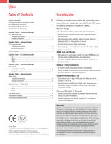
Designed to provide customers with the widest selection of sizes, orifices and construction materials, Series 2700 meets the exacting demands of the process industry. Superior Design A single design handles air, steam, vapor and liquid services. Maximum interchangeability of parts affords easy maintenance and lower costs. Fixed blowdown design simplifies testing and repair. Maximum blowdown of 5% to 15% regardless of service.1 A built-in lift stop ensures stable performance. Balanced design in “C” and “D” orifices nullifies the effects of back pressure on set point. ASME Code Certification Manufactured...
Open the catalog to page 2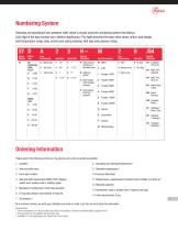
Numbering System Selecting and specifying Farris pressure relief valves is simple using the numbering system that follows. Each digit of the type number has a distinct significance. The digits describe the basic valve series, orifice, seat design, inlet temperature range, body, bonnet and spring material, inlet type and pressure rating. Special Variations Inlet Connections Special Materials Series Number Orifice Area Seat Construction H High pressure variations of standard types B Balanced design3 D Heat transfer fluid standard pressure E Heat transfer fluid high pressure M1 Monel Body & Disc...
Open the catalog to page 3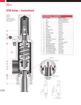
2700 Series – Conventional Bill of Materials – Conventional Item Complies with ASME Boiler & Pressure Vessel Code, Section VIII Part Name Bonnet Disc Guide Disc Holder Stem Spring Adj. Screw Jam Nut Cap, Plain Screwed Cap Gasket Body Gasket Guide Gasket Spring (-50°F to +750°F) Spring Buttons Wire Seal Nameplate (Not Shown) Welding Nipple (Inlet) Welding Nipple (Outlet) Lap Joint Stub End (Inlet) Lap Joint Stub End (Outlet) Lap Joint Flange (Inlet) Lap Joint Flange (Outlet) Standard Material SA-351, Gr. CF8M St. St. or SA-479 Type 316 St. St. SA-216, Gr. WCB, Carb. St. 316 St. St. 316 St. St....
Open the catalog to page 4
2700 Series – Balanced Design Complies with ASME Boiler & Pressure Vessel Code, Section VIII Do you have variable back pressure? Can’t use a balanced bellows design? Farris has the solution with the Series 2700 Balanced Design pressure relief valve. The balanced effect is achieved by isolating the upper valve chamber and eliminating any back pressure build-up in the bonnet effecting valve set pressure. These valves are available in 1/2", 3/4" and 1" inlet sizes with a 1" outlet and two orifice areas. Pressure ranges from 15 to 1480 psig, standard soft seat design. Flanged and welded inlet and...
Open the catalog to page 5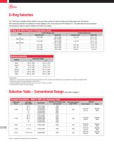
O-Ring Selection The 2700 Series is available with an optional O-ring seat which minimizes fugitive emissions and costly product loss. This optional seat construction provides zero bubbles per minute leakage at 90% of set pressure per API Standard 527. The tables below list the set pressure and temperature range for both the elastomer and Teflon seat options. O-Ring Seat Valve Pressure & Temperature Limits Pressure Range, psig1 Elastomer Seat Teflon Seat C High Pressure D High Pressure E F G Pressure Range, barg1 Elastomer Seat Teflon Seat Material Availability Material Viton® Buna N EPR Silicone...
Open the catalog to page 6
Selection Table – Conventional Design Flanged Connections, U.S. Customary Units Orifice Area Sq. In. Valve Size Inlet x Outlet ANSI Flange Class Inlet RF Maximum Set Pressure, psig Type Number Max. Back Pressure psig at 100°F Materials Body / Bonnet Stainless Steel Stainless Steel Stainless Steel Stainless Steel Stainless Steel Stainless Steel Stainless Steel Stainless Steel Stainless Steel General Notes: 1. vailable with optional elastomer or Teflon seat design as illustrated. Change the fourth digit of the type number from “A” to “C” for soft seat, “A” to “T” for Teflon. Example: A 27DC23-M20...
Open the catalog to page 7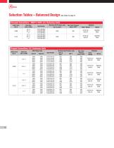
Selection Tables – Balanced Design (see notes on page 5) Threaded Connections – MNPT X FNPT, U.S. Customary Units Orifice Area Sq. In. Valve Size Inlet x Outlet Type Number Maximum Set Pressure, psig -20°F to 450°F Max. Back Pressure psig at 100°F Stainless Steel Stainless Steel Materials Body / Bonnet Spring Flanged Connections, U.S. Customary Units Orifice Area Sq. In. Valve Size Inlet x Outlet ANSI Flange Class Inlet RF Type Number Maximum Set Pressure, psig -20°F to 400°F 100°F Max. Back Pressure psig at 100°F Materials Body / Spring Bonnet Stainless Steel Stainless Steel Stainless Steel...
Open the catalog to page 8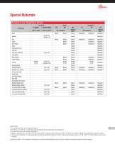
Special Materials Corrosive & Low Temperature Service Part Name Disc Guide Disc Holder Stem Spring Adj. Screw Jam Nut Cap, Plain Screwed Cap Gasket Body Gasket Guide Gasket Spring Buttons O-Ring Retainer5 Retainer Lock Screw5 O-Ring Seat Seal5 Guide Seal5 Disc Holder Seal5 Wire Seal Nameplate (Not Shown) Welding Nipple (Inlet) Welding Nipple (Outlet) Lap Joint Stub End (Inlet) Lap Joint Stub End (Outlet) Lap Joint Flange (Inlet)4 Lap Joint Flange (Outlet)4 Monel Monel Monel 316 St. St. Monel Monel Inconel X-750 Monel Monel Monel Monel Monel Monel Monel Monel Monel Monel Monel Monel Monel Monel...
Open the catalog to page 9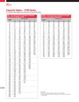
Capacity Tables – 2700 Series U.S. Customary Units: ASME Pressure Vessel Code, Section VIII (UV) Stamp AIR – 10% Overpressure Capacities in Standard Cubic Feet Per Minute at 60°F Set Pressure (psig) STEAM – 10% Overpressure Capacities in Pounds Per Hour at Saturation Temperature Set Pressure (psig) General Notes: 1. apacities at 30 psig and below are based on 3 psi overpressure. C 2. or sizing purposes, the coefficients of discharge K are 0.878 for air, gas & steam; F 0.676 for water.
Open the catalog to page 10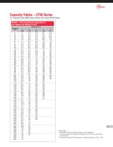
Capacity Tables – 2700 Series U.S. Customary Units: ASME Pressure Vessel Code, Section VIII (UV) Stamp WATER – 10% Overpressure Capacities3 in U.S. Gallons Per Minute at 70°F Set Pressure (psig) 9 General Notes: 1. apacities at 30 psig and below are based on 3 psi overpressure. C 2. or sizing purposes, the coefficients of discharge K are 0.878 for air, gas & steam; F 0.676 for water. 3. o determine capacity at 25% overpressure, multiply the capacity at 10% by 1.066. T
Open the catalog to page 11All Farris Engineering catalogs and technical brochures
 Farris engineering
8 Pages
 nuclear product
4 Pages

Archived catalogs
 Universal test stand
1 Page
 Authorized Service team
4 Pages
 Size master
2 Pages
 Serie 2856
2 Pages
 Serie 6400-6600
8 Pages
 Serie 2850
2 Pages
 Serie 4200
16 Pages
 Serie 1896M
2 Pages
 Serie 1890
2 Pages
 Serie 3800
24 Pages
