- Catalogs
- Farris Engineering
- 2600 series : Pressure Relief Valves
2600 series : Pressure Relief Valves
1 /96Pages

2600 series : Pressure Relief Valves
1 /96Pages
Catalog excerpts

Pressure Relief Valves 'Flow Control Company Farris Engineering
Open the catalog to page 1
Introduction This catalog covers Series 2600, 2600S and 2600L pressure relief valves including the latest infor ation available to assist m you in the sizing and selection of the proper valves for your application. Farris pressure relief valves have over a half century of proven performance providing auto atic and positive m protection against overpressure in thousands of industrial plants and facilities worldwide. Our earned reputation as “the First Line of Safety” is the result of countless Farris innovations combined with progressive engineering, sound design and high quality production....
Open the catalog to page 3
The Farris Advantage Farris pressure relief valves are designed to automatically protect your equipment against excessive overpressure. Every care is taken in the development, design and production of these valves to ensure complete dependability in performance. Our constant objective is to provide a superior valve that will assure ultimate protection at the lowest cost, both initially and throughout its service life. What is the Farris Advantage? Easy sizing and selection of valves using Farris catalogs and/or SizeMaster™ Sizing and Selection software. A method of specification and ordering...
Open the catalog to page 4
2600 Series Design Valve Selection This catalog simplifies the sizing and selection of Series 2600 process pressure relief valves. The pressure relief valves are presented here in an easy-to-understand format. Unless otherwise stated, references made to the Code refer specifically to ASME Section VIII, Division 1. Certified Capacity Code Compliance The Series 2600 pressure relief valves have been carefully constructed and tested in accordance with the requirements of the ASME Pressure Vessel Code, Section VIII. Their capacity rating for the applicable fluids is certified by the National Board...
Open the catalog to page 5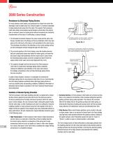
2600 Series Construction Resistance to Discharge Piping Strains For most pressure relief valves, and particularly for those from which the discharge must be piped away to a remote location, it is almost impossible to keep piping strains away from the valve. The superior Farris pressure relief valve design incorporates several features which allow this valve to take a maximum amount of piping strain without hampering the functional characteristics of the valve or contributing to serious leakage. 1. The threaded connection between the valve nozzle and the valve inlet flange is located low in the...
Open the catalog to page 6
2600 Series Metallurgy Integral Sleeve Guide The Farris pressure relief valve design incorporates an integral sleeve guide (Fig 5), assuring continual positive alignment after the part has been manufactured, and including the same high corrosion resistant properties in the guide flange that are present in the sleeve portion of the guide. The sleeve guide is extended above the top of the guide flange, minimizing the possibility of corrosive or other foreign particles washing onto the guiding surfaces when the valve is relieving or when it is “breathing” as a result of atmospheric temperature changes....
Open the catalog to page 7
2600 Series Operation All Stainless Steel Stem Construction The Farris pressure relief valve design features an all stainless steel stem. This construction cost-effectively eliminates dangerous sticking due to galvanic corrosion at the upper guiding point in the spring adjusting screw. The careful design of this upper bearing also ensures proper alignment and optimum freedom from galling and erratic popping. Positive Connection of Parts The Farris design incorporates a positive connection between the valve stem and the stem retainer as well as between the disc and disc holder (Fig 7). These connections...
Open the catalog to page 8
2600 Series Operation Steam Jacketing for Better Heat Transfer In modern process plants, it is necessary to keep some valves and lines warm at all times to avoid solidification of the lading fluid and to guarantee the safety of equipment. Farris offers a steam jacket (Fig 8) to substantially increase the rate of heat transfer into the valve and, at the same time, simplify the problem of removing or dismantling the valve for maintenance. This design offers a separate two-piece jacket that installs on a standard valve body. See details on page 71. Simple, Accurate Adjustments The single Blow Down...
Open the catalog to page 9
General Technical Information Standard Flanged Connections 1. All steel raised face flanges are supplied with a serrated spiral finish with 45 to 55 grooves per inch and a finish between 125 and 160 AARH. 2. All ring joint flanged facings are supplied for octagonal or oval gaskets. 3. Facings other than raised face or large male can be supplied at additional cost. 4. Flange ratings that conform to ANSI B16.5 are indicated on each Orifice Selection Table. Heavier outlet flanges can be supplied at additional cost. For flange dimensions, see ANSI Dimension Table, page 77. 5. Drilling of all flanges...
Open the catalog to page 10
Definitions Safety Valve – an automatic pressure relieving device actuated by the static pressure upstream of the valve, and characterized by rapid full opening or pop action. Used for steam, gas or vapor service. Relief Valve – an automatic pressure relieving device actuated by the static pressure upstream of the valve, which opens in proportion to the increase in pressure over the opening pressure. Safety Relief Valve – an automatic pressure actuated relieving device suitable for use as either a safety or relief valve, depending on the application. Pressure Relief Valve – a pressure relief...
Open the catalog to page 11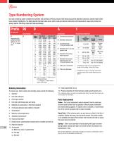
Type Numbering System Our type numbering system simplifies the selection and specifying of Farris pressure relief valves because the digits that comprise a specific type number have a distinct significance. The digits describe the basic valve series, orifice, seat and internal construction, inlet temperature range, body, bonnet and spring material, inlet flange class and Code liquid design. H Designates high pressure versions. Used for “Q”, “R”, “T”, & “U” orifices only. Series Number Orifice Areas Orifice Letter E BalanSeal with auxiliary balancing piston F BalanSeal with auxiliary balancing...
Open the catalog to page 12All Farris Engineering catalogs and technical brochures
 Serie 2700
20 Pages
 Farris engineering
8 Pages
 nuclear product
4 Pages
Archived catalogs
 Universal test stand
1 Page
 Authorized Service team
4 Pages
 Size master
2 Pages
 Serie 2856
2 Pages
 Serie 6400-6600
8 Pages
 Serie 2850
2 Pages
 Serie 4200
16 Pages
 Serie 1896M
2 Pages
 Serie 1890
2 Pages
 Serie 3800
24 Pages
