


- Company
- Products
- Catalogs
- News & Trends
- Exhibitions
SIR-A
SIR-A
- Activation and Deactivation Levels: Functions activate at 100% and deactivate at 95%.
- Timing Accuracy: ±30 ms or ±5% for IEC/IEEE curves, ±35 ms or ±0.5% for defined time curves.
- Function 64REF: Current tap from 0.050 to 20.000 xIn, time delay from 0.020 to 300.000 seconds.
- Function SOTF: Current tap from 0.010 to 30.000 xIn, time delay from 0.000 to 295.000 seconds.
- Function 50INC: Phase current tap from 0.500 to 20.000 xIn, with pickup and trip peaks.
- Function 49: Current tap from 0.100 to 2.400 In, with heating and cooling parameters.
- Function SHB: Current tap from 5 to 50%, with reset time settings.
- Function CLP: Settings for no load and cold load times, with breaker activation and reset thresholds.
- Function 46: Supports IEC and IEEE curves, with time delay and current tap settings.
- Function 46BC: Tap settings from 15 to 100%, with time delay settings.
- Function 37: Current tap from 0.010 to 30.000 xIn, with minimum level settings.
- Function 27-1 and 27-2: Voltage tap from 0.04 to 2.00 xUn, with time delay and reset settings.
- Function 59-1 and 59-2: Voltage tap settings with time delay and reset settings.
- Function 81 Series: Frequency functions with activation levels and time delay settings.
- Function 79: Reclose settings with multiple times and locking options.
- Function 52: Monitors circuit breaker status with opening and closing times.
- Programmable Logic Control (PGC): Includes logic functions like OR, AND, XOR.
- Disturbance Fault Recording (DFR): Configurable records in COMTRADE format.
- Load Data Profiling (LDP): Power demand recording with configurable rates.
- Digital input voltage range of 75-265 Vdc / 55-265 Vac available upon request.
- Firmware version 1.21.00 or later required for certain features.
- Not all feature combinations are possible; confirmation with the manufacturer is necessary.
Catalog excerpts
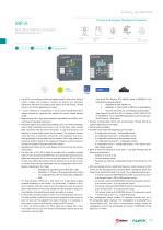
SIR-ARECLOSER CONTROL & FEEDER PROTECTION RELAY Primary & Secondary Distribution Protection E©©© (c) ^Std. CTs /1 ;'5 Voltage sensors) KEMA Labs • The SIR-A is an overhead control and feeder protection relay which includes current, voltage, and frequency functions for primary and secondary distribution, fitted with an auxiliary power supply of 24-230 Vdc/ac, 48-230 Vdc/ac or 24-48 Vdc (depending on model). • 4 current channels for conventional /1 and /5 current transformers and 6 voltage channels for capacitive and resistive low power voltage sensors (LEAs). • Metal housing with a high electromagnetic compatibility level (EMC) and a wide range of operating temperature. • Protection against decoupling, load shedding, and Loss of Main (islanding). Loss of Main (islanding) occurs when a part of the public utility network loses connection with the rest of the system. In case this situation is not detected, a network safety hazard can be present if the generator remains connected since an automatic reconnection of the generator may occur, causing damage to the generator and the network. SIR-A relay detects this hazardous situation thanks to its voltage and frequency functions based on the Rate Of Change Of Frequency (ROCOF) method. • Signalling and control of the circuit breaker (52 function) and the recloser (79 function). • The front part of the SIR-A relays is provided with a navigation keypad made of 7 keys (including the RESET key), 6 programmable hot keys that by default are configured: two (2) keys to open and close the CB, two (2) keys to block and unblock the recloser and two (2) keys to put the relay in local or remote mode with their associated three (3) configurable control LEDs. Besides, depending on the model: o Adaptation B: Eight (8) programmable alarm LEDs o Adaptation C: Thirteen (13) programmable alarm LEDs + 8 configurable keys with their associated configurable LED. • Arc Flash detection (AFD) with 4 AFD inputs and 4 high-speed outputs (available depending on the model). This functionality, in addition to Wi-Fi communication, allows the users to set and configure the relay through the SICom free software of Fanox and operate the relay remotely far away from the installation, thus prioritizing the health and safety of workers. • In case a CB is manually closed, a switch on to an existing fault may occur. This fault condition is critical if the overcurrent protection function does not clear the fault until the adjusted time delay is finished. It is necessary, in those cases, to clear the fault quickly through the SOTF function. • To allow the communication, the SIR-A relays are provided with a local micro-USB front port and with remote communication options (ports and protocols) on the rear side: » Rear Serial Port: Modbus RTU, DNP3.0 Serial or IEC60870-5-103 (selectable by general settings). o Adaptation B: Rear RS485 port. o Adaptation C: Rear RS485 or RS232 port (selectable by the user; both ports are not available simultaneously). » Rear Ethernet Port (RJ45 or FO-LC): Modbus TCP/IP, DNP3.0 TCP/ IP, IEC60870-5-104 or IEC61850 (selectable by general settings) + SNTP Protocol + Web Server. • Wireless communication (Wi-Fi) and synchronization through IRIG-B are optional (depending on the model). • Alarms panel is available. • The SIR-A is provided with (depending on the model): » 8 configurable inputs and 7 configurable outputs. » 24 configurable inputs and 7 configurable outputs. » 8 configurable inputs and 18 configurable outputs. » 16 configurable inputs and 11 configurable outputs. » 8 configurable inputs, 7 configurable outputs, 4 AFD inputs, and 4 High-Speed outputs. • SIR-A is fitted with demand of power (LDP - Load Data Profiling) with the following characteristics: » Circular recording mode. » Sampling rate (interval): configurable through communications (1-60 min). • SIR-A is provided with non-volatile RAM memory in order to store up to 3072 events and the disturbance fault recording (DFR), maintaining date & time thanks to its internal RTC (Real Time Clock). The configurable options are: » 5 records in data and COMTRADE format (300 cycles each record): 1 to 8 pre-fault cycles + 292 to 299 post-fault cycles. » 25 records in data and COMTRADE format (60 cycles each record): 1 to 8 pre-fault cycles + 52 to 59 post-fault cycles. » 50 records in data and COMTRADE format (30 cycles each record): 1 to 8 pre-fault cycles + 22 to 29 post-fault cycles. » 100 records in data and COMTRADE format (15 cycles each record): 1 to 8 pre-fault cycles + 7 to 14 post-fault cycles. • Each oscillographic record contains 10 analogue channels and up to 96 configurable digital channels. The oscillography is downloaded by a communications port. The SICom communications program allows the oscillography record to be downloaded and saved in COMTRADE format (IEEE C37.111-1991).
Open the catalog to page 1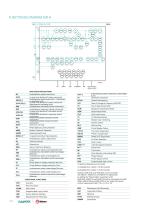
FO* IRIG-B* WIFI* ETHERNET* USB Rear serial port*: ANSI CODE PROTECTIONS Instantaneous phase overcurrent Inverse time directional* phase overcurrent Instantaneous phase overcurrent - Adjustment Inverse time directional* phase overcurrent - .Adjustment by reclosing cycle Instantaneous calculated neutral overcurrent Instantaneous measured neutral overcurrent Inverse time directional* calculated neutral Inverse time directional* measured neutral Directional isolated calculated neutral Directional isolated measured neutral Phase balance current protection Broken Conductor Detection Restricted Earth...
Open the catalog to page 2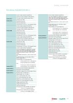
TECHNICAL PARAMETERS SIR-A Function 67N/51N-1 Function 67N/51N-2
Open the catalog to page 3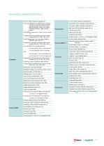
TECHNICAL PARAMETERS SIR-A 51/67[79] (*) Function enable: No/Alarm/Trip/SHB Trip Function SOTF
Open the catalog to page 5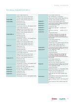
TECHNICAL PARAMETERS SIR-A Function 59N-1
Open the catalog to page 7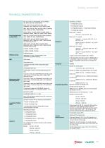
TECHNICAL PARAMETERS SIR-A Programmable logic control (PGC)
Open the catalog to page 9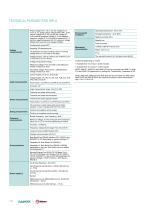
(*) Optional depending on model (1) Available from fw version 1.22.00 onwards. (2) Available from fw version 1.23.00 onwards. NOTE: ANSI 67, ANSI 67G and ANSI 67N can be converted into ANSI 51, ANSI 51G and ANSI 51N respectively by setting the “Directionality” parameter to NO. NOTE: ANSI 50G, ANSI 67G and ANSI 67GI will be converted into ANSI 50GS, ANSI 67GS and ANSI 67GSI in the model with neutral current measurement digit 1 (IN = 0.1A or 1A)
Open the catalog to page 10All FANOX ELECTRONIC catalogs and technical brochures
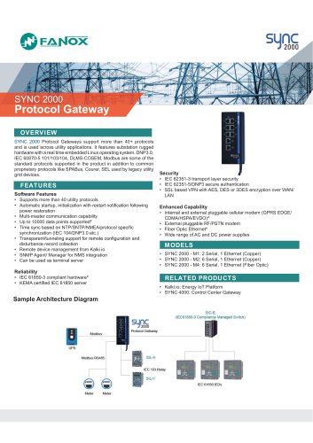 SYNC 2000 Protocol Gateway
2 Pages
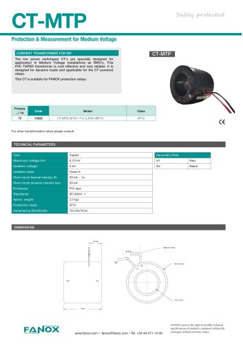 CT-MTP
1 Page
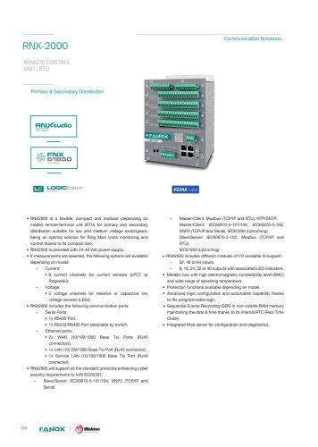 RNX-2000
9 Pages
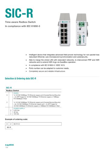 SIC-R
SIC-R2 Pages
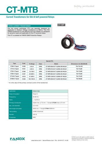 CT-MTB
1 Page
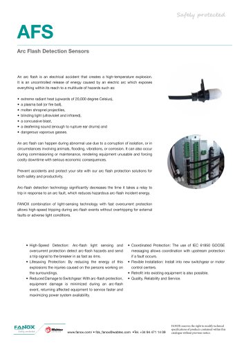 AFS
AFS3 Pages
 Fanox Overview Protection Relays
68 Pages
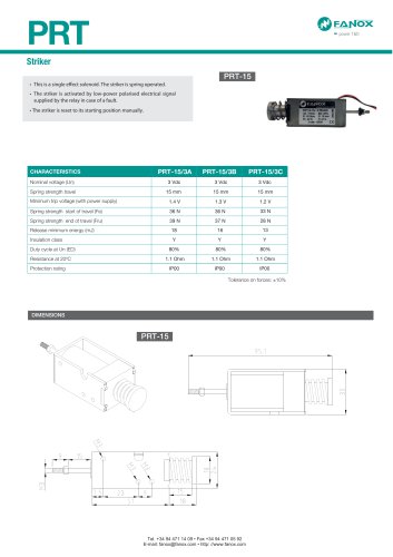 PRT
PRT1 Page
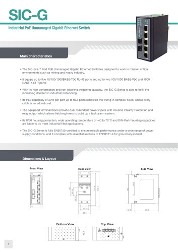 SIC-G
SIC-G4 Pages
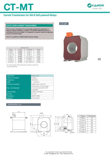 CT-MT
CT-MT1 Page




- FANOX dry transformer
- Surge protector
- Switching relay
- DIN rail lightning arrester
- Communication gateway
- Class II surge protector
- Fieldbus gateway
- Ethernet gateway
- FANOX encapsulated transformer
- Single-phase transformer
- Serial gateway
- Industrial transformer
- Low-voltage transformer
- Time relay
- Class II surge arrester
- Plug-in lightning arrester
- FANOX instrument transformer