Catalog excerpts

RENEWABLE ENERGY Energy Efficient Components for PV Solar Systems
Open the catalog to page 1
As global demand for electrical energy continues to grow, so has the need for alternative energy sources that minimize impact on the environment. The generation of clean ("green") energy has become increasingly viable due to the latest process technology system topologies and components. Photovoltaic power generation is forecasted to have a significant impact in the global power equation, and has been demonstrated to be economically viable and technologically feasible. Recent advances in photovoltaic cell technology, coupled with the recent availability of high efficiency, high performance,...
Open the catalog to page 3
. BOOST CONVERTER AND THREE-LEVEL INVERTER NEUTRAL POINT CLAMPED (NPC) FOR NON-REACTIVE . BOOST CONVERTER AND THREE-LEVEL INVERTER NEUTRAL POINT CLAMPED (NPC) FOR REACTIVE
Open the catalog to page 4
SOLAR ENERGY HARVESTING SYSTEMS Central Inverter Central inverters convert the DC voltage from "strings" of photovoltaic (PV) panels to AC voltage. They are residential, commercial and utility scale systems with a power level of 1 kW or higher. The * maximum power point tracking (MPPT) for the PV panels is performed centrally at the DC-AC inverter stage. *Maximum power point tracking (MPPTj is a technique which solar power systems use in order to achieve the maximum possible power from the PV array. Solar cells have a complex relationship between solar irradiation, temperature and total...
Open the catalog to page 5
SOLAR ENERGY HARVESTING SYSTEMS Micro Inverter Installed on each PV panel, micro inverters process power for one panel only (typically less than 300W). Each micro inverter includes both the DC-DC and DC-AC inverter stage. The advantages of this configuration include scalability as well as distributed MPPT to optimize each PV panel. The MPPT for the PV panels is performed centrally at the inverter stage. DC-DC Converter Stage PV-Side AUX Power DC Link DC-AC Inverter Stage Drivers Protection & Grid Interface AC Link Drivers 12V 5V 3.3V V/I Monitor V/I Monitor MPPT Control DC-DC Control V/I...
Open the catalog to page 6
PV PANEL CONFIGURATION SYSTEMS Design Options for Energy Harvesting Designers of energy harvesting systems have many options and have to make many critical design tradeoffs when defining the architecture of their system. The decision as to whether the MPPT function will be performed in a central or distributed manner is fundamental and often dictated by efficiency complexity and cost considerations. This choice also has implications on whether the DC-AC conversion will be performed centrally or distributed. And finally various cell serial or parallel configurations are also possible....
Open the catalog to page 7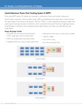
PV PANEL CONFIGURATION SYSTEMS CentraI-Maxim urn Power Point Tracking System (C-MPPT) In the central-MPPT systems, PV modules are connected in combinations of series and parallel configurations. The PV modules connected in series are called "strings" MPPT can be performed at the system level or at the string level. The output voltage of each string can be between 150V and 1 000VDC. In order to generate the peak grid voltage, ih systems need a boost step (converter or transformer), which is performed at the output of the string. Single-stage inverters (using full-bridge or neutral-point...
Open the catalog to page 8
PV PANEL CONFIGURATION SYSTEMS Distributed-Maximum Power Point Tracking System (D-MPPT) In low power (1 90W-380VV) distributed-MPPT systems, such as the micro inverter and micro converter architectures, the MPPT is performed at each PV module. These low power systems can be integrated into the frame of the PV module. The micro inverter is often called an "AC-module" and the micro converter is often called a "DC-Optimizer." D-MPPT Options The on-demand D-MPPT function is performed only for shaded PV modules. The output voltage of the shaded PV modules is reduced and the DC current is kept...
Open the catalog to page 9
SOLAR ENERGY HARVESTING TOPOLOGIES_ _CENTRAL INVERTER (TRADITIONAL INVERTER) Boost Converter and Full-Bridge Inverter (Topology 1) This non-isolated topology can handle a wide MPPT range by using a boost converter stage paired with a single-stage inverter. If the input voltage is higher than DC-link voltage, the boost converter stage will not operate. Instead, the bypass diode will conduct to provide input power to inverter stage. This topology can achieve higher efficiency than the isolated inverter. Boost Stage Inverter Stage Q2, Q4 and Q5 can be replaced with IGBTs. Fairchild's solutions...
Open the catalog to page 10
SOLAR ENERGY HARVESTING TOPOLOGIES CENTRAL INVERTER (TRADITIONAL INVERTER) Phase Shifted Full-Bridge Converter and Full-Bridge Inverter (Topology 2) The high voltage gain transformer provides a wide MPPT range and isolation between the PV module and the grid. This topology typically has lower efficiency, compared to the boost converter and full-bridge inverter topology. In order to achieve higher efficiency some systems utilize "tapped transformers." Depending on the input voltage, the turns ratio of the transformer can be adjusted in order to achieve higher efficiency. Isolated DC-DC...
Open the catalog to page 11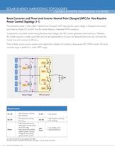
SOLAR ENERGY HARVESTING TOPOLOGIES_ CENTRAL INVERTER (TRADITIONAL INVERTER) Boost Converter and Three-Level Inverter Neutral Point Clamped (NPC) for Non-Reactive Power Control (Topology 3-1) The three-level inverter is often called "Neutral Point Clamped" (NPC) because the output voltage is clamped to the neutral point level by diodes D3 and D4, thus the inverter delivers a three-level PWM waveform. Compared to a two-level inverter having the same input voltage, the NPC inverter generates lower harmonics. Therefore, this inverter requires a smaller output filter and can be implemented at a...
Open the catalog to page 12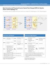
SOLAR ENERGY HARVESTING TOPOLOGIES CENTRAL INVERTER (TRADITIONAL INVERTER) Boost Converter and Three-Level Inverter Neutral Point Clamped (NPC) for Reactive Power Control (Topology 3-2) This three-level inverter can handle reactive power with the use of diodes D5, D6 (left diagram) or Q3, Q4 (right diagram). Boost Stage Boost Stage Requirements (Left Diagram) Ql, Q4, Q5 and Q6 can be replaced with IGBTs. Fairchild's solutions meet these requirements; see pages 17-27 for further information. Q5 and Q6 can be replaced with IGBTs. Fairchild's solutions meet these requirements; see pages 17-27...
Open the catalog to page 13All Fairchild Semiconductor catalogs and technical brochures
-
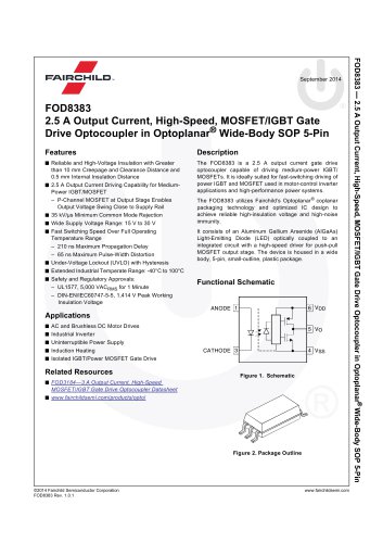
FOD8383 2.5 A Output Current
18 Pages
-
Logic SELECTION GUIDE
12 Pages
-
Automotive Solutions Guide
8 Pages
-
Motor Drive Solution Guide
20 Pages
-
Mobile Solutions Guide
40 Pages
-
AUTOMOTIVE SOLUTIONS
16 Pages
-
Power Solutions Guide
60 Pages
-
STANDARD PRODUCTS GUIDE
72 Pages
Archived catalogs
-
3:1 Analog Switch Products
2 Pages
-
USB Multimedia Switches
2 Pages
-
Analog switch & interface
12 Pages
-
Mobile overview
4 Pages
-
TinyLogic® Product Overview
4 Pages
-
Optocoupler Solutions
24 Pages
-
Motor DRIVE solutions
32 Pages
-
LED LIGHTING SOLUTIONS
16 Pages
-
DIGITAL DISPLAY SOLUTIONS
36 Pages
-
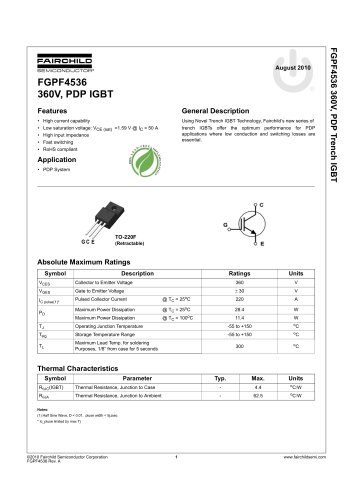
FGPF4536 360V, PDP IGBT
8 Pages
-
FSAR001B AC-DC Linear Regulator
12 Pages
-
Fairchild - Power solutions
52 Pages


