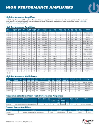
ISL9V3040S3ST 17A, 400V Logic Level, Voltage Clamped, Avalanche Energy Rated, ESD Protected IGBT
8Pages

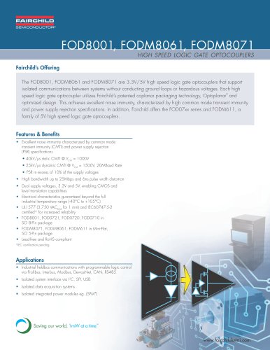
Catalog excerpts
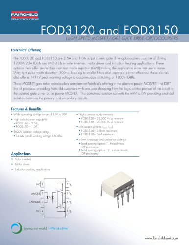
©2009 Fairchild Semiconductor Corporation ISL9V3040D3S / ISL9V3040S3S / ISL9V3040P3 / ISL9V3040S3 ISL9V3040D3S / ISL9V3040S3S / ISL9V3040P3 / ISL9V3040S3 EcoSPARK 300mJ, 400V, N-Channel Ignition IGBT General Description The ISL9V3040D3S, ISL9V3040S3S, ISL9V3040P3, and ISL9V3040S3 are the next generation ignition IGBTs that offer outstanding SCIS capability in the space saving D-Pak (TO-252), as well as the industry standard D²-Pak (TO-263), and TO-262 and TO- 220 plastic packages. This device is intended for use in automotive ignition circuits, specifically as a coil driver. Internal diodes provide voltage clamping without the need for external components. devices can be custom made to specific clamp voltages. Contact your nearest Fairchild sales office for more information. Formerly Developmental Type 49362 Applications • Automotive Ignition Coil Driver Circuits • Coil- On Plug Applications Features • Space saving D-Pak package availability • SCIS Energy = 300mJ at TJ = 25oC • Logic Level Gate Drive Device Maximum Ratings TA = 25°C unless otherwise noted Symbol Parameter Ratings Units BVCER Collector to Emitter Breakdown Voltage (IC = 1 mA) 430 V BVECS Emitter to Collector Voltage - Reverse Battery Condition (IC = 10 mA) 24 V ESCIS25 At Starting TJ = 25°C, ISCIS = 14.2A, L = 3.0 mHy 300 mJ ESCIS150 At Starting TJ = 150°C, ISCIS = 10.6A, L = 3.0 mHy 170 mJ IC25 Collector Current Continuous, At TC = 25°C, See Fig 9 21 A IC110 Collector Current Continuous, At TC = 110°C, See Fig 9 17 A VGEM Gate to Emitter Voltage Continuous ±10 V PD Power Dissipation Total TC = 25°C 150 W Power Dissipation Derating TC > 25°C 1.0 W/°C TJ Operating Junction Temperature Range -40 to 175 °C TSTG Storage Junction Temperature Range -40 to 175 °C TL Max Lead Temp for Soldering (Leads at 1.6mm from Case for 10s) 300 °C Tpkg Max Lead Temp for Soldering (Package Body for 10s) 260 °C ESD Electrostatic Discharge Voltage at 100pF, 1500Ù 4 kV Package GATE COLLECTOR EMITTER R2 R1 Symbol JEDEC TO-252AA D-Pak D²-Pak JEDEC TO-263AB COLLECTOR (FLANGE) JEDEC TO-220AB E G E G JEDEC TO-262AA E G C E G C November 2009 ® EcoSPARK® • Qualified to AEC Q101 • RoHS Compliant ISL9V3040D3S / ISL9V3040S3S / ISL9V3040P3 / ISL9V3040S3 Rev. D4, November 2009
Open the catalog to page 1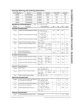
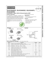
ISL9V3040D3S / ISL9V3040S3S / ISL9V3040P3 / ISL9V3040S3 Package Marking and Ordering Information Electrical Characteristics TA = 25°C unless otherwise noted Off State Characteristics On State Characteristics Dynamic Characteristics Switching Characteristics Thermal Characteristics Device Marking Device Package Reel Size Tape Width Quantity V3040D ISL9V3040D3ST TO-252AA 330mm 16mm 2500 V3040S ISL9V3040S3ST TO-263AB 330mm 24mm 800 V3040P ISL9V3040P3 TO-220AA Tube N/A 50 V3040S ISL9V3040S3 TO-262AA Tube N/A 50 V3040D ISL9V3040D3S TO-252AA Tube N/A 75 V3040S ISL9V3040S3S TO-263AB Tube N/A 50...
Open the catalog to page 2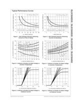
ISL9V3040D3S / ISL9V3040S3S / ISL9V3040P3 / ISL9V3040S3 Typical Performance Curves Figure 1. Self Clamped Inductive Switching Current vs Time in Clamp Figure 2. Self Clamped Inductive Switching Current vs Inductance Figure 3. Collector to Emitter On-State Voltage vs Junction Temperature Figure 4. Collector to Emitter On-State Voltage vs Junction Temperature Figure 5. Collector to Emitter On-State Voltage vs Collector Current Figure 6. Collector to Emitter On-State Voltage vs Collector Current tCLP, TIME IN CLAMP (ìS) ISCIS, INDUCTIVE SWITCHING CURRENT (A) 25 15 5 30 20 10 0 RG = 1kÙ, VGE =...
Open the catalog to page 3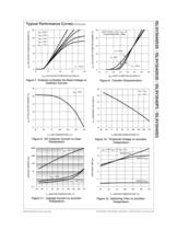
ISL9V3040D3S / ISL9V3040S3S / ISL9V3040P3 / ISL9V3040S3 Typical Performance Curves (Continued) Figure 7. Collector to Emitter On-State Voltage vs Collector Current Figure 8. Transfer Characteristics Figure 9. DC Collector Current vs Case Temperature Figure 10. Threshold Voltage vs Junction Temperature Figure 11. Leakage Current vs Junction Temperature Figure 12. Switching Time vs Junction Temperature ICE, COLLECTOR TO EMITTER CURRENT ( A) VCE, COLLECTOR TO EMITTER VOLTAGE (V) 25 15 5 0 20 10 0 1.0 2.0 3.0 4.0 VGE = 4.0V VGE = 3.7V VGE = 4.5V VGE = 5.0V VGE = 8.0V TJ = 175°C ICE, COLLECTOR...
Open the catalog to page 4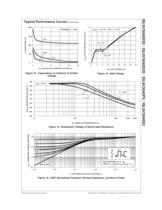
ISL9V3040D3S / ISL9V3040S3S / ISL9V3040P3 / ISL9V3040S3 Typical Performance Curves (Continued) Figure 13. Capacitance vs Collector to Emitter Voltage Figure 14. Gate Charge Figure 15. Breakdown Voltage vs Series Gate Resistance Figure 16. IGBT Normalized Transient Thermal Impedance, Junction to Case C, CAPACITANCE (pF) VCE, COLLECTOR TO EMITTER VOLTAGE (V) 1600 800 400 1200 0 5 10 15 20 25 0 CIES COES CRES FREQUENCY = 1 MHz QG, GATE CHARGE (nC) VGE, GATE TO EMITTER VOLTAGE (V) 0 2 4 8 0 4 8 12 16 20 24 28 3 5 7 6 1 32 IG(REF) = 1mA, RL = 1.25Ù, TJ = 25°C VCE = 6V VCE = 12V BVCER, BREAKDOWN...
Open the catalog to page 5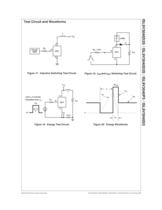
ISL9V3040D3S / ISL9V3040S3S / ISL9V3040P3 / ISL9V3040S3 Test Circuit and Waveforms Figure 17. Inductive Switching Test Circuit Figure 18. tON and tOFF Switching Test Circuit Figure 19. Energy Test Circuit Figure 20. Energy Waveforms RG G C E VCE L PULSE GEN DUT RG = 1KÙ + - DUT VCE 5V C G E LOAD R or L tP VGE 0.01Ù L IAS + - VCE VDD RG VARY tP TO OBTAIN REQUIRED PEAK IAS 0V DUT G C E VDD VCE BVCES tP IAS tAV 0 ©2009 Fairchild Semiconductor Corporation ISL9V3040D3S / ISL9V3040S3S / ISL9V3040P3 / ISL9V3040S3 Rev. D4, November 2009
Open the catalog to page 6
© 2009 Fairchild Semiconductor Corporation www.fairchildsemi.com TRADEMARKS The following includes registered and unregistered trademarks and service marks, owned by Fairchild Semiconductor and/or its global subsidiaries, and is not intended to be an exhaustive list of all such trademarks. AccuPower™ Auto-SPM™ Build it Now™ CorePLUS™ CorePOWER™ CROSSVOLT™ CTL™ Current Transfer Logic™ EcoSPARK® EfficientMax™ EZSWITCH™* ™* DEUXPEED™ ® Fairchild® Fairchild Semiconductor® FACT Quiet Series™ FACT® FAST® FastvCore™ FETBench™ FlashWriter®* FPS™ F-PFS™ FRFET® Global Power ResourceSM Green FPS™...
Open the catalog to page 8All Fairchild Semiconductor catalogs and technical brochures
-
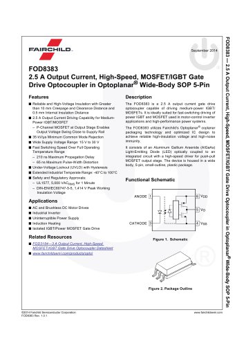
 FOD8383 2.5 A Output Current
18 Pages
-
 Logic SELECTION GUIDE
12 Pages
-
 Automotive Solutions Guide
8 Pages
-
 Motor Drive Solution Guide
20 Pages
-
 Mobile Solutions Guide
40 Pages
-
 AUTOMOTIVE SOLUTIONS
16 Pages
-
 Power Solutions Guide
60 Pages
-
 STANDARD PRODUCTS GUIDE
72 Pages


Archived catalogs
-
 3:1 Analog Switch Products
2 Pages
-
 USB Multimedia Switches
2 Pages
-
 Analog switch & interface
12 Pages
-
 Mobile overview
4 Pages
-
 TinyLogic® Product Overview
4 Pages
-
 Optocoupler Solutions
24 Pages
-
 Motor DRIVE solutions
32 Pages
-
 LED LIGHTING SOLUTIONS
16 Pages
-
 DIGITAL DISPLAY SOLUTIONS
36 Pages
-
 RENEWABLE ENERGY SOLUTIONS
32 Pages
-
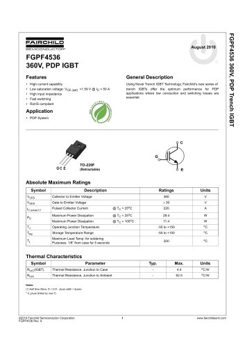 FGPF4536 360V, PDP IGBT
8 Pages
-
 FSAR001B AC-DC Linear Regulator
12 Pages
-
 Fairchild - Power solutions
52 Pages