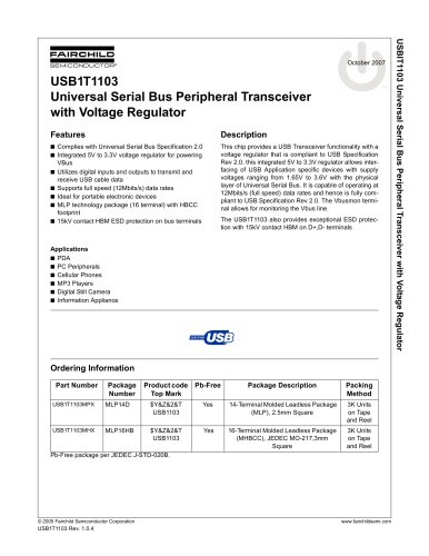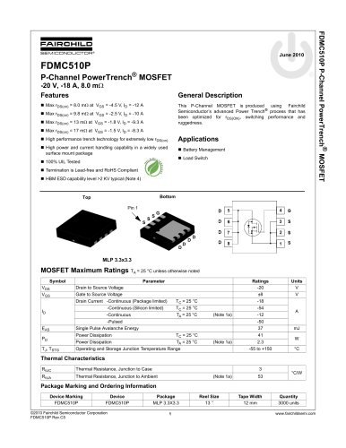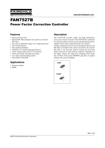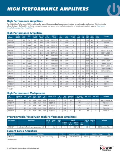
Catalog excerpts
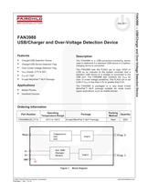
May 2011 © 2007 Fairchild Semiconductor Corporation www.fairchildsemi.com FAN3988 • Rev. 1.0.10 FAN3988 — USB/Charger and Over-Voltage Detection Device FAN3988 USB/Charger and Over-Voltage Detection Device Features „X Charger/USB Detection Device „X Charger/USB Device Detection Flag „X Over-/Under-Voltage Detection Flag „X VBUS Supply: 2.7V to 20V „X CON of 1.5pF „X 6-Lead MicroPak™ MLP Package Applications „X Mobile Phones „X Handheld Devices Description The FAN3988 is a USB-connection-monitoring device used to determine if a standard USB device or a batterycharging device is connected. The FAN3988 sets the FLAG1 pin to logic HIGH or LOW as an indicator to the system controller that a standard USB device or a charger is connected to the USB port. The FAN3988 also monitors the VBUS for over- or under-voltage conditions. The FLAG2 pin is set LOW if VBUS is less than 3.3V or greater than 6.0V. The FAN3988 is packaged in a very small 6-lead MicroPak™ MLP package suitable for small board space applications, such as mobile phones. Ordering Information Part Number Operating Temperature Range Package Packing Method Quantity FAN3988IL6X_F113 -40°C to +85°C 6-Lead MicroPak™ MLP Package Reel 3000 Figure 1. Block Diagram Flag 1 Comparator OVP UVP Flag 2 DVbus Logic GND Std USB/ Charger D+ Detect Logic
Open the catalog to page 1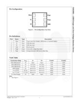
© 2007 Fairchild Semiconductor Corporation www.fairchildsemi.com FAN3988 • Rev. 1.0.10 2 FAN3988 — USB/Charger and Over-Voltage Detection Device Pin Configuration Figure 2. Pin Configuration (Top View) Pin Definitions Pin# Name Type Description 1 Vbus Input Power input from charger, USB device, or handheld battery 2 D- Input USB data input 3 D+ Input USB data input 4 Gnd Input Device ground 5 Flag2 Output Over/under-voltage flag output 6 Flag1 Output Charger/standard USB device detect flag Truth Table Connection State VBUS D- D+ FLAG1 FLAG2 STD USB Device(1) 0V Open Open LOW LOW STD USB...
Open the catalog to page 2
© 2007 Fairchild Semiconductor Corporation www.fairchildsemi.com FAN3988 • Rev. 1.0.10 3 FAN3988 — USB/Charger and Over-Voltage Detection Device Absolute Maximum Ratings Stresses exceeding the absolute maximum ratings may damage the device. The device may not function or be operable above the recommended operating conditions and stressing the parts to these levels is not recommended. In addition, extended exposure to stresses above the recommended operating conditions may affect device reliability. The absolute maximum ratings are stress ratings only. Symbol Parameter Min. Max. Unit VBUS DC...
Open the catalog to page 3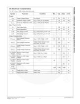
© 2007 Fairchild Semiconductor Corporation www.fairchildsemi.com FAN3988 • Rev. 1.0.10 4 FAN3988 — USB/Charger and Over-Voltage Detection Device DC Electrical Characteristics TA = 25°C, VBUS = 5.0V, unless otherwise noted. Symbol Parameter Condition Min. Typ. Max. Unit Supply VBUS Supply Voltage Range VBUS Range 2.7 5.0 20.0 V IBUS Quiescent Supply Current VBUS = +5.0V, D+ D- Shorted 1.2 2.0 mA tSUPPLY Power-Up Stabilization Time VBUS = +5.0V, D+ D- Shorted 10 ms Input Characteristics CD+ Input Capacitance 1.5 2.0 pF CD- Input Capacitance 1.5 2.0 pF Ioff D+ Off Leakage Current VBUS = 0V or...
Open the catalog to page 4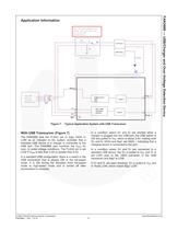
© 2007 Fairchild Semiconductor Corporation www.fairchildsemi.com FAN3988 • Rev. 1.0.10 6 FAN3988 — USB/Charger and Over-Voltage Detection Device Application Information Figure 7. Typical Application System with USB Transceiver With USB Transceiver (Figure 7) The FAN3988 sets the FLAG1 pin to logic HIGH or LOW as an indicator to the system controller that a standard USB device or a charger is connected to the USB port. The FAN3988 also monitors the VBUS for over- or under-voltage conditions. The FLAG2 pin is set LOW if VBUS is less than 3.3V or greater than 6.0V. In a standard USB...
Open the catalog to page 6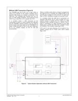
© 2007 Fairchild Semiconductor Corporation www.fairchildsemi.com FAN3988 • Rev. 1.0.5 7 Without USB Transceiver (Figure 8) The FAN3988 sets the FLAG1 pin to logic HIGH or LOW as an indicator to the system controller that a standard USB device or a charger is connected to the USB port. The FAN3988 also monitors the VBUS for over- or under-voltage conditions. The FLAG2 pin is set LOW if VBUS is less than 3.3V or greater than 6.0V. In a condition where a USB transceiver is not incorporated or there is a switch between the USB port and the FAN3988, external resistors must be used to set the...
Open the catalog to page 7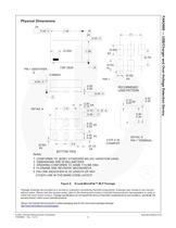
© 2007 Fairchild Semiconductor Corporation www.fairchildsemi.com FAN3988 • Rev. 1.0.10 8 FAN3988 — USB/Charger and Over-Voltage Detection Device Physical Dimensions Figure 9. 6-Lead MicroPak™ MLP Package Package drawings are provided as a service to customers considering Fairchild components. Drawings may change in any manner without notice. Please note the revision and/or date on the drawing and contact a Fairchild Semiconductor representative to verify or obtain the most recent revision. Package specifications do not expand the terms of Fairchild’s worldwide terms and conditions,...
Open the catalog to page 8
© 2007 Fairchild Semiconductor Corporation www.fairchildsemi.com FAN3988 • Rev. 1.0.10 9 FAN3988 — USB/Charger and Over-Voltage Detection Device
Open the catalog to page 9All Fairchild Semiconductor catalogs and technical brochures
-
FOD8383 2.5 A Output Current
18 Pages
-
Logic SELECTION GUIDE
12 Pages
-
Automotive Solutions Guide
8 Pages
-
Motor Drive Solution Guide
20 Pages
-
Mobile Solutions Guide
40 Pages
-
AUTOMOTIVE SOLUTIONS
16 Pages
-
Power Solutions Guide
60 Pages
-
STANDARD PRODUCTS GUIDE
72 Pages
Archived catalogs
-
3:1 Analog Switch Products
2 Pages
-
USB Multimedia Switches
2 Pages
-
Analog switch & interface
12 Pages
-
Mobile overview
4 Pages
-
TinyLogic® Product Overview
4 Pages
-
Optocoupler Solutions
24 Pages
-
Motor DRIVE solutions
32 Pages
-
LED LIGHTING SOLUTIONS
16 Pages
-
DIGITAL DISPLAY SOLUTIONS
36 Pages
-
RENEWABLE ENERGY SOLUTIONS
32 Pages
-
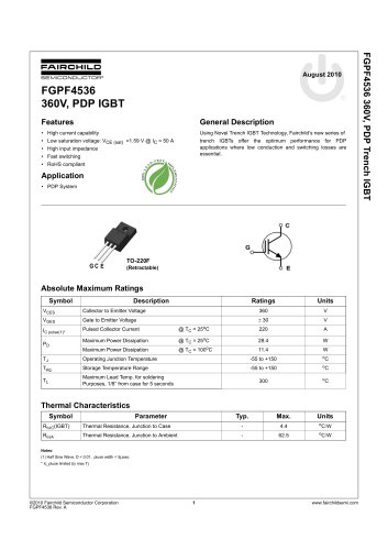
FGPF4536 360V, PDP IGBT
8 Pages
-
FSAR001B AC-DC Linear Regulator
12 Pages
-
Fairchild - Power solutions
52 Pages


