Group: Gilbarco Veeder-Root

Catalog excerpts
The VISY-X system serves the purpose of measuring and evaluating the fillinglevels in filling station tanks for mineral oil fuels. Use the system for this purpose only. The manufacturer shall not be liable for any form of damage resulting from improper use of this system!The VISY-View display was developed, manufactured and inspected in accordancewith state-of-the-art technology and with recognised safety rules and regulations. Nevertheless, hazards may arise from the use of this unit. Therefore, observe the following safety instructions:Do not change or modify the system or add any...
Open the catalog to page 4
The VISY-View display stands on two nonslip feet in order to ensure unproblematicoperation of the buttons.The front operator side is screwed at an angle with the feet so that user-friendlyoperation is ensured. The operator interface comprises the display screen (1) and five operator buttons (48). For the indication of operating statuses, the VISY- View unit is equipped with two pilot lamps (2֖3). (see Fig. 1) > 13456782 AlarmPower " which moves upand down on the left side in the display screen and marks specific lines, and the Left-Right cursor ">" which pages through the menu items at the...
Open the catalog to page 5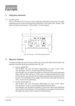
2.1On-Off switchThe on-off switch (9) is found on the underside of the device (see Fig. 1b). After installing and turning on the device by using the on-off switch, the "Power" LED lights up green (see section "Pilot lamps" in this chapter). > 9 To page through the various menu items and call up the desired tank data, five operator buttons (48) are available (see Fig. 1a): Cursor up/left (8)This button has two functions depending on each cursor form:The Up-Down cursor is moved upward by this button.Accordingly, you can select a submenu in the main menu and individual menu items in the...
Open the catalog to page 6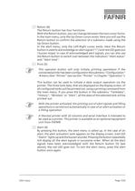
Return (6)The Return button has four functions:With the Return button, you can change between the two cursor forms.In the main menu, only the Up-Down cursor exists. Here you will use the Return button to confirm the selection of a submenu made using the Up-Down button. In the alert menu, only the Left-Right cursor exists. Here the Return button is used to acknowledge an alert signal ("!") and red LED goes out / buzzer stops). In case of acknowledged alert signals, you can also use the Return button to switch over between the indication "Alert status" and "Alert time". Print (5) This...
Open the catalog to page 7
3.1Key switchThrough connection 13 (see Fig. 2) an accessible key switch can be mounted for use by tanker drivers in case the filling station has already closed. Before refilling, a repetitive turning of the key switch will bring the relevant data of all the tanks one after another onto the display screen. Which three tank data for a tank should be displayed are selected in sub menu "Configuration" under "DspTruck" menu point (see section "Truck display" in Chapter "Operation"). > The VISY-View display is equipped with a green LED "Power" (2) and a red LED "Alarm" (3) in order to indicate...
Open the catalog to page 8
10Connection to appropriate power supply unit included in the scope ofsupplies11֖Alert outputs (11a = output 1, 11b = output 2) The two alert outputs can be configured so that a potential-freetransistor is closed for a specific alert status or for all alert statuses (seeChapter "Putting into operation" and loading limits in Chapter"Technical data"). When connecting the alert outputs the correct polarities must beobserved ("+" for connections 1 or3). If the poles are confused thenthe contact is always closed! 12RS485 interface for connection to the control unit VISY-Command13֖Remote input...
Open the catalog to page 9
In order to put the VISY-View display into service, proceed as follows:1.First chose which interface of the control unit VISY-Command will be used toconnect the display VISY-View. The display VISY-View is connected to the host interface of the controlunit VISY-Command when no other host system (e. g. POS system) will be connected. If the host interface of VISY-Command is already used byanother device, VISY-View must be connected to the extension interfaceof VISY-Command. 2.Use the configuration software VISY-Setup to configure the interfaces of VISY-Command (see separate operating...
Open the catalog to page 10
Old rating plate up to device number 524 Fig. 3: Rating plates VISY-View New rating plate from device number 525 With devices from no. 525, terminal 7 can be used, if required, to applya cable screening or for potential equalisation with the RS485 interfacesof connected devices. Terminal 7 may not be connected to earthpotential, as there is the danger of potential equalisation currents which are too high and could damage the interface. 4.Connect a printer as required to the 9-pin Sub-D socket. A thermal printer with 32 columns and serial interface is intended tobe used as a printer. This...
Open the catalog to page 11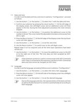
1.1Date and timeIn order to set the date and time, and once in submenu "Configuration", proceedas follows:1.Use the button or the button to select line 1 with the date and time.2.Confirm your selection by pressing the return button . At the left edge ofthe display screen, the Left-Right cursor and an additional cursor will thenappear in the line. During the time adjustment procedure the clock remains stopped.3.Use the button or the button to position the additional cursor on thenumber to be set. The cursor marks the adjustable time data continuously from left to right.4.Press the Return...
Open the catalog to page 13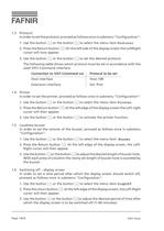
1.3ProtocolIn order to set the protocol, proceed as follows once in submenu "Configuration":1.Use the button or the button to select the menu item Protocol .2.Press the Return button . On the left side of the display screen the LeftRightcursor will now appear.3.Use the button or the button to set the desired protocol.The following table shows which protocol must be set in accordance with theused VISY-Command interface: Host interfaceHost-108 Extension interfaceExt. Prot.1.4PrinterIn order to set the printer, proceed as follows once in submenu "Configuration":1.Use the button Connection to...
Open the catalog to page 14All FAFNIR catalogs and technical brochures
-
 TORRIX M12 MOBILE
2 Pages
-
 TORRIX XTS
2 Pages
-
 TORRIX 6
1 Pages
-
 LPG Sensors
8 Pages
-
 SEPARIX
8 Pages
-
 Process Automation
28 Pages
-
 O²-PID
4 Pages
-
 COMS Leaflet
4 Pages
-
 VAPORIX Flow and Control
40 Pages
-
 Wallmounting Typ 907
4 Pages
-
 QE 200
4 Pages
-
 UM 2.1/2.2/2.3
20 Pages
-
 TORRIX HART
28 Pages
-
 TORRIX RS485 Modbus
16 Pages
-
 TORRIX M12
40 Pages
-
 FAFNIR Hart Setup
9 Pages
-
 LS 300 / 500
7 Pages
-
 76 A / NB 220
5 Pages
-
 76 / NB 220
2 Pages
-
 SECON-X
4 Pages
-
 PRESSURIX
12 Pages
-
 Insite360
4 Pages
-
 Plugs
Plugs12 Pages
-
 UM 2.1/UM 2.2/UM 2.3
20 Pages
-
 TORRIX-HART
28 Pages
-
 DIVELIX
8 Pages
-
 CONDURIX-HART
28 Pages
-
 CONDURIX
24 Pages
-
 VAPORIX
12 Pages
-
 VISY-X
24 Pages
-
 Accessories
3 Pages
-
 VISY-Command Web
4 Pages
-
 VISY-Reed
4 Pages
-
 VISY-RF
2 Pages
-
 VISY-Stick
15 Pages
-
 VISY-TD Display
2 Pages
-
 VISY-View Touch
2 Pages
-
 VPI - VISY-Power Interface
1 Pages
-
 TORRIX
10 Pages
-
 TORRIX CI
1 Pages
-
 TORRIX RS485
3 Pages
-
 UM-X Transducer
3 Pages
-
 TEMPERIX
8 Pages
-
 HPH Ex d
3 Pages
-
 VISY-Monitor
2 Pages
-
 VISY-Input VISY-Output
4 Pages
-
 VISY-Command
5 Pages
-
 LPG-Sensoren
8 Pages


Archived catalogs
-
 2019 VISY-Stick Flex
2 Pages
-
 2016 VISY-Stick Flex
2 Pages
-
 VISY-X LON
10 Pages
-
 SEPARIX
23 Pages
-
 VAPORIX Flow/Control
32 Pages
-
 VISY-Setup V 3.1.0
40 Pages
-
 VISY-Setup V2.10
42 Pages
-
 VISY-Stick and VISY-Command
24 Pages
-
 Overfill Prevention (GWG)
12 Pages


