 Website:
FAFNIR
Group: Gilbarco Veeder-Root
Catalog excerpts

Technical Documentation
Open the catalog to page 1
The high-precision TORRIX level sensor is designed to provide continuous gauging of liquid media levels in tanks. The measuring principle used by the sensor exploits the physical effect of magnetostriction and is largely unaffected by temperature. This method is particularly ideal where level measurements are required to be extremely accurate, such as in the chemical industry. In this documentation, the TORRIX is described as a variant with M12 plug connector. As another option, the TORRIX with cable gland is available, see: Technical documentation TORRIX, art. no. 207074 The TORRIX with...
Open the catalog to page 4
Safety instructions The purpose of the TORRIX level sensor is to gauge liquid levels in tanks. The level sensor must be used exclusively for this purpose. The manufacturer accepts no liability for any form of damage resulting from improper use. The level sensor has been developed, manufactured and tested in accordance with the latest good engineering practices and generally accepted safety standards. Nevertheless, hazards may arise from its use. For this reason, the following safety instructions must be observed: Do not change or modify the level sensor or add any equipment without the...
Open the catalog to page 5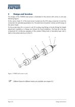
The design of the TORRIX level sensor is illustrated in the version with screw-in unit (see following figure). At the sensor head (1) of the level sensor located are the M12 plug connector (2) and the connection for potential equalization (3). The electrical connection is done via M12 plug on the sensor head. On the probe tube (4) is a screw-in unit (5) (cutting ring fitting or ferrule fitting) for height adjustment capability or a flange (not shown) for fixed installation. The float (6) is the key component for continuous gauging of the product filling level or boundary layer and is held...
Open the catalog to page 6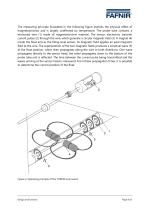
The measuring principle illustrated in the following figure exploits the physical effect of magnetostriction and is largely unaffected by temperature. The probe tube contains a tensioned wire (1) made of magnetostrictive material. The sensor electronics transmit current pulses (2) through the wire, which generate a circular magnetic field (3). A magnet (4) inside the float acts as the filling level sensor. Its magnetic field applies an axial magnetic field to the wire. The superposition of the two magnetic fields produces a torsional wave (5) at the float position, which then propagates...
Open the catalog to page 7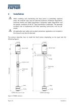
Installation When installing and maintaining the level sensor in potentially explosive areas, the national rules must be observed (Explosion Protection Regulations, Industrial Health and Safety Regulations, Equipment Safety Regulations and the specific conditions of the EC-Type Examination Certificates). The generally accepted rules of engineering and these operating instructions must be observed. All applicable local safety and accident prevention regulations not included in this manual must also be observed. This section describes how to install the level sensor depending on the type (see...
Open the catalog to page 8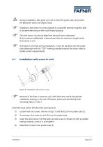
During installation, take great care not to bend the probe tube, and protect the float from shock and impact loads. Installing a level sensor in areas exposed to a powerful external magnetic field is not permitted because this could impair gauging. The level sensor can also be fitted into the tank from underneath. If the container additionally is pressurized, then the maximum length of the level sensor is 2 m. If the float is removed during installation, it must be slid back onto the probe tube afterwards with the “TOP” marking oriented towards the sensor head to enable correct...
Open the catalog to page 9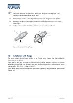
For correct gauging, the float must be slid onto the probe tube with the “TOP” marking oriented towards the sensor head. Refit circlip (1) on the tube, align the set screws with the groove and tighten. Adjust the height of the process connection and fix the union nut (5) by hand finger-tight. Fix the union nut (5) with a 1 ¼ clockwise turn (see following figure). 5 Figure 5: Compression fitting fixing Installation with flange The probe tube is permanently welded to the flange, which means that the installation length cannot be altered. The screws or nuts and the seals are the responsibility...
Open the catalog to page 10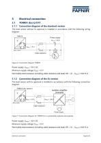
Electrical connection Connection diagram of the standard version The level sensor without Ex approval is installed in accordance with the following wiring diagram: TORRI X Power supply Spannungsquelle Umax = 50 V Leitungswiderstände Cable resistance Load Bürde U Figure 6: Connection diagram TORRIX Power supply: Umax = 50 V DC Minimum supply voltage: Umin = 8 V Permissible total resistance (including cable resistance and load): ΣR = (U - Umin) / 0.0215 A Connection diagram of the Ex version The level sensor with Ex approval is installed in accordance with the following connection diagram:...
Open the catalog to page 11
FAFNIR The intrinsically safe version of the TORRIX Ex C level sensor, when installed in a potentially explosive atmosphere, is permitted to be connected only to associated equipment that have been certified by a recognised inspection authority and offer electrical outputs that meet the following conditions: Uo < 30 V data can be found in the EC-Type Examination Certificate (refer to the Appendix). If the level sensor is to be used in a potentially explosive atmosphere, always make sure that the permissible external capacitance (C0) and inductance (L0) of the associated equipment are not...
Open the catalog to page 12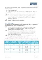
The connection cable between the TORRIX ... and the associated equipment must have the following properties: • 2-wire unshielded cable For Ex applications colour blue or marked blue (cable for intrinsically safe power circuits) The earthing or equipotential bonding must be carried out by the installer in accordance with the national installation regulations applicable in each case. The earth connector of the sensor head can be used for earthing or equipoten-tial bonding requirements. Note also the general installation regulations. 5.1.4 Cable length The maximum cable length depends on the...
Open the catalog to page 13All FAFNIR catalogs and technical brochures
-
TORRIX M12 MOBILE
2 Pages
-
TORRIX XTS
2 Pages
-
TORRIX 6
1 Pages
-
LPG Sensors
8 Pages
-
SEPARIX
8 Pages
-
Process Automation
28 Pages
-
O²-PID
4 Pages
-
COMS Leaflet
4 Pages
-
VAPORIX Flow and Control
40 Pages
-
Wallmounting Typ 907
4 Pages
-
QE 200
4 Pages
-
UM 2.1/2.2/2.3
20 Pages
-
TORRIX HART
28 Pages
-
TORRIX RS485 Modbus
16 Pages
-
FAFNIR Hart Setup
9 Pages
-
LS 300 / 500
7 Pages
-
76 A / NB 220
5 Pages
-
76 / NB 220
2 Pages
-
SECON-X
4 Pages
-
PRESSURIX
12 Pages
-
Insite360
4 Pages
-
Plugs
12 Pages
-
UM 2.1/UM 2.2/UM 2.3
20 Pages
-
TORRIX-HART
28 Pages
-
DIVELIX
8 Pages
-
CONDURIX-HART
28 Pages
-
CONDURIX
24 Pages
-
VAPORIX
12 Pages
-
VISY-X
24 Pages
-
Accessories
3 Pages
-
VISY-Command Web
4 Pages
-
VISY-Reed
4 Pages
-
VISY-RF
2 Pages
-
VISY-Stick
15 Pages
-
VISY-TD Display
2 Pages
-
VISY-View Touch
2 Pages
-
VPI - VISY-Power Interface
1 Pages
-
TORRIX
10 Pages
-
TORRIX CI
1 Pages
-
TORRIX RS485
3 Pages
-
UM-X Transducer
3 Pages
-
TEMPERIX
8 Pages
-
HPH Ex d
3 Pages
-
VISY-Monitor
2 Pages
-
VISY-Input VISY-Output
4 Pages
-
VISY-Command
5 Pages
-
LPG-Sensoren
8 Pages
Archived catalogs
-
2019 VISY-Stick Flex
2 Pages
-
2016 VISY-Stick Flex
2 Pages
-
VISY-X LON
10 Pages
-
SEPARIX
23 Pages
-
VAPORIX Flow/Control
32 Pages
-
VISY-Setup V 3.1.0
40 Pages
-
VISY-Setup V2.10
42 Pages
-
VISY-View
24 Pages
-
VISY-Stick and VISY-Command
24 Pages
-
Overfill Prevention (GWG)
12 Pages


