 Website:
FAFNIR
Group: Gilbarco Veeder-Root
Catalog excerpts
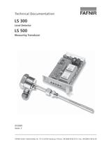
Technical Documentation LS 300 > Level Detector LS 500 > Measuring Transducer 07/2005Issue: 2 FAFNIR GmbH Bahrenfelder Str. 19 Օ D-22765 Hamburg Phone: +49 (0)40-39 82 07-0 Օ Fax: +49 (0)40-3 90 63 39 size="-4">
Open the catalog to page 1
The specialised company or operator of the system may only use such systemparts without inspection symbols that comply with the national regulations.ՕIn case of failure of the auxiliary power supply (exceeding or dropping belowthe limit values) or in case of interruption of the connecting lines between the system parts, level detector type LS 300. with measuring transducer LS 500. must report this fault or indicate the maximum filling level.The safety instructions in this manual are labelled as follows: If you fail to observe these safety instructions, there is a risk of anaccident or the...
Open the catalog to page 6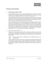
C ambienttemperature) to two minutes (at -20 The level detector consists of a sensor (encapsulated PTC resistor) and a probetube which can be adjusted in height with a clampable screw-in unit is permanently mounted using a flange (see figs. 2aЖd and chap. "Installation").The encapsulated PTC resistor serves for detecting the liquid level. Detecting theliquid level is the purpose of the encapsulated PTC resistor in the form of a varying resistance at the threshold point of the level detector, the resistance value of which increases with rising temperature (see figs. 2a2d).Since liquids...
Open the catalog to page 7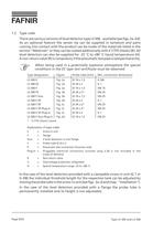
1.2Type codeThere are various versions of level detector type LS 300. available (see figs. 2a2d):As an optional feature the sensor tip can be supplied in tantalum and parts coming into contact with the product can be made of the materials listed in the section "Materials" or they can be coated additionally with E-CTFE (Halar) (B). All level detectors can also be supplied for -25 ְ C to +80 C liquid temperature (H).A non-return valve (R) is compulsory if the pneumatic test pipe is laid permanently. When being used in a potentially explosive atmosphere the specialconditions in the EC type...
Open the catalog to page 8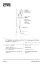
Junction boxtype DD 28pin assignment1 and 6 for sensors 13 and 4 for sensors 1 Threshold lengthspermanentlyimprinted Threshold point 2 Threshold point 1(overfill prevention) Flange acc. to DIN or ASAconnection dimensionsacc. to DIN 2501excludeddesigns L and Mor equivalent foreign standards > 24Threshold length (max. 3000 mm)Threshold length 2 (max. 3000 mm)125 12 >
Open the catalog to page 12
1.5ApplicationLevel detector type LS 300. is operated under the below mentioned conditionsin tanks for the storage of combustible and non-combustible, water-endan- gering liquids from which no permanent deposits are to be expected.Ambient conditionsTemperature:-20 հ C to +60 CPressure:0.8 bar to 1.1 barЕDeviating conditionsLiquid temperature Normal temperature:-25 C to +50 а CSpecial temperature:-25 C to +80 а CPressureStandard pressure range:0 to 4 bar Special version:0 to 26 barDeviations, e.g. 0 C to +80 а C, stated on the rating plate. If the sensor tip cools down on account of...
Open the catalog to page 13
With the exception of type LS 500 Duo, there is an alarm relay with anLED available as an option. If there is an interruption or a short circuitin the signal line between the level detector and the measuring transducer, the relay attracts and the "Fault" LED lights up. The measuring transducer consists of evaluation electronics for the PTC resistor ofthe level detector, potential-free changeover contacts for connecting to a control system or a power factor as well as signal lamps inside the housing.The evaluation electronic converts the resistance changes at the PTC resistor torelay...
Open the catalog to page 14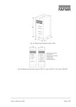
Sensor > 150 Scanner#Fault Power >
Open the catalog to page 15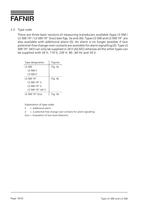
Type designationFiguresLS 500Fig. 3aLS 500 SLS 500 ZLS 500 19Fig. 3bLS 500 19ӓ SLS 500 19 ZLS 500 19ӓ AK 5LS 500 19 DuoFig. 3bExplanation of type codes > S=Additional alarmZ=2 potential-free change-over contacts for alarm signallingDuo=Evaluation of two level detectors Type LS 300 and LS 500Page 16/33 >
Open the catalog to page 16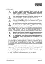
For all work performed on the level detector type LS 300. andmeasuring transducer LS 500., observe the national safety andaccident prevention regulations as well as all the safety instructionsin this manual of operating instructions. To set up and operate the system, the generally recognised rules ofengineering and these operating instructions are applicable. During installation of the level detector the sensor may only be in anintensive vapour flow if it is provided with a protective sleeve against excessive vapour movement. The measuring transducer may not be operated in potentially...
Open the catalog to page 17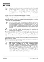
When the level detector has been installed, the correct adjustment ofthe threshold length (L) can be checked, without removing the sensor,by means of the reference dimension (Y) (= distance between themarking groove at the top end of the probe tube and the hexagon support of the screw-in unit) and the imprinted probe length (Z).L=Z Y In order to lock the probe tube in place, proceed as follows:֕Tighten the upper gland screw and the locking screw of the screw-in unitfirmly.Provide the screw-in thread with suitable, resistant sealing material and screwit into the tank muff provided for it....
Open the catalog to page 18
If there is no overvoltage protection, the overvoltage protection typeBA 350 must be fitted close to the level detector (approx. 50 cm). Anexternal earthing terminal is provided for the electrical connection(4mm > 2 cable) between the housing and the tank. Prior to putting into service, all the devices in the system must bechecked with respect to correct connection and proper operation. In addition, the electrical power supply, including that of the downstreamdevices, must also be checked. For this purpose observe the relevantoperating instructions for the devices being used. > Type LS 300...
Open the catalog to page 19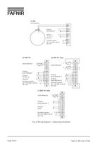
Level detectorOutputlevel detectorOutput"S" or "Z"(option)Auxiliary power24, 110, 230 V, 50 Hz 24 V DC 01020607090910111213 1415 PEL1 (+)N (-) d 020406081012 14 161820222426283032 > z 12 > d 02040608101214 161820222426283032 > z Outputlevel detectorLevel detectorOutput"S" or "Z" (option)Auxiliary power24, 110, 230 V, 50 Hz 24 V DC Output level detector 1Output level detector 2Level detector Auxiliary power24, 110, 230 V, 50 Hz 24 V DC > PEL1 (+)N (-) PEL1 (+)N (-) d 020406081012 1416 18 20 22 24 26283032 > z Outputlevel detector 1OutputfaultLevel detector Auxiliary power24, 110, 230 V, 50...
Open the catalog to page 20All FAFNIR catalogs and technical brochures
-
TORRIX M12 MOBILE
2 Pages
-
TORRIX XTS
2 Pages
-
TORRIX 6
1 Pages
-
LPG Sensors
8 Pages
-
SEPARIX
8 Pages
-
Process Automation
28 Pages
-
O²-PID
4 Pages
-
COMS Leaflet
4 Pages
-
VAPORIX Flow and Control
40 Pages
-
Wallmounting Typ 907
4 Pages
-
QE 200
4 Pages
-
UM 2.1/2.2/2.3
20 Pages
-
TORRIX HART
28 Pages
-
TORRIX RS485 Modbus
16 Pages
-
TORRIX M12
40 Pages
-
FAFNIR Hart Setup
9 Pages
-
LS 300 / 500
7 Pages
-
76 A / NB 220
5 Pages
-
76 / NB 220
2 Pages
-
SECON-X
4 Pages
-
PRESSURIX
12 Pages
-
Insite360
4 Pages
-
Plugs
12 Pages
-
UM 2.1/UM 2.2/UM 2.3
20 Pages
-
TORRIX-HART
28 Pages
-
DIVELIX
8 Pages
-
CONDURIX-HART
28 Pages
-
CONDURIX
24 Pages
-
VAPORIX
12 Pages
-
VISY-X
24 Pages
-
Accessories
3 Pages
-
VISY-Command Web
4 Pages
-
VISY-Reed
4 Pages
-
VISY-RF
2 Pages
-
VISY-Stick
15 Pages
-
VISY-TD Display
2 Pages
-
VISY-View Touch
2 Pages
-
VPI - VISY-Power Interface
1 Pages
-
TORRIX
10 Pages
-
TORRIX CI
1 Pages
-
TORRIX RS485
3 Pages
-
UM-X Transducer
3 Pages
-
TEMPERIX
8 Pages
-
HPH Ex d
3 Pages
-
VISY-Monitor
2 Pages
-
VISY-Input VISY-Output
4 Pages
-
VISY-Command
5 Pages
-
LPG-Sensoren
8 Pages
Archived catalogs
-
2019 VISY-Stick Flex
2 Pages
-
2016 VISY-Stick Flex
2 Pages
-
VISY-X LON
10 Pages
-
SEPARIX
23 Pages
-
VAPORIX Flow/Control
32 Pages
-
VISY-Setup V 3.1.0
40 Pages
-
VISY-Setup V2.10
42 Pages
-
VISY-View
24 Pages
-
VISY-Stick and VISY-Command
24 Pages
-
Overfill Prevention (GWG)
12 Pages


