 Website:
FAFNIR
Group: Gilbarco Veeder-Root
Catalog excerpts

Technical Documentation
Open the catalog to page 1
© Copyright: Reproduction and translation are permitted only with the written consent of the FAFNIR GmbH. FAFNIR GmbH reserves the right to make changes to products without prior notice.
Open the catalog to page 3
The purpose of the CONDURIX level sensor is to provide continuous level gauging of electrically conductive liquids (> 1 μS/cm). During the measurement no insulating layer must be formed on the probe tube. The level sensor is available in lengths of 200 to 6,000 mm. With the “single-rod probe” model (CONDURIX Mono), the inside of the container must have a conductive surface (metal containers / downpipes). The “two-rod probe” model (CONDURIX DU) or “jacketed probe” model (CONDURIX MA) are both compatible with non-conductive containers. The standard sensors work by outputting the measured fill...
Open the catalog to page 4
Safety instructions The purpose of the CONDURIX level sensor is to provide continuous level gauging of liquids. The level sensor must be used exclusively for this purpose. The manufacturer accepts no liability for any form of damage resulting from improper use. The level sensor has been developed, manufactured and tested in accordance with the latest good engineering practices and generally accepted safety standards. Nevertheless, hazards may arise from its use. For this reason, the following safety instructions must be observed: Do not change or modify the level sensor or add any equipment...
Open the catalog to page 5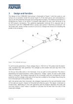
The design of the CONDURIX level sensor is illustrated in Figure 1 with the screw-in unit version as an example. Inside the sensor head (1) of the level sensor and concealed by a cap (2) are the protected terminals and configuration buttons. The electrical connection is established by means of an M16x1.5 screwed cable gland (3) and screw terminals or by an M12 plug-in connection. The potential equalization terminal (4) is required only in conjunction with the CONDURIX Mono version (see section 5 Electrical connection). On the probe neck, there is either a screw-in unit (5) or a flange (not...
Open the catalog to page 6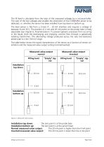
The fill level is calculated from the ratio of the measured voltages by a microcontroller. The ratio of the two voltages also enables the orientation of the CONDURIX sensor to be detected, i.e. whether the sensor has been installed from top down or bottom up. The level sensor is fed from a 2-wire 4 … 20 mA interface and requires a voltage of between 8 and 30 V. The position of 4 mA and 20 mA points on the probe tube is freely adjustable (see chapter 6, Parametrisation). To prevent galvanic processes from occurring in the liquid, both the discharging and charging currents flow through a...
Open the catalog to page 7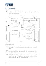
Installation All local safety and accident prevention regulations not expressly referred to herein must be observed. Cable gland M16x1.5 Sensor head Sensor head Probe tube ∅6 Counter electrode ∅ 24 Measuring range Probe tube Flange or screw-in unit R 2 Installation length Jacketed pipe Screw-in unit R ¾ min. or flange Measuring range Connector for equipotential bonding Installation length Connector for equipotential bonding Adjustment range Measuring range Figure 3: CONDURIX variants Level gauging with CONDURIX is possible only in electrically conductive liquids. The level sensor can also...
Open the catalog to page 8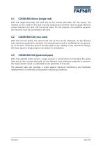
CONDURIX Mono (single rod) With the single-rod probe, the tank acts as the counter electrode. For this reason, the material on the inside of the tank must be conductive and there must be good electrical contact between the tank and the sensor head. For this purpose, the potential equalization terminal must be connected to the tank. With the two-rod probe, the second rod acts as the counter electrode. As the distance from reference potential is constant, the measurement result is unaffected by the geometry of the tank. While the second rod also adds to the stability of the mechanical design,...
Open the catalog to page 9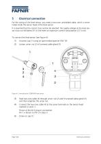
Electrical connection For the wiring of the level sensor, you need a two-core unshielded cable, which is terminated inside the sensor head of the level sensor. It is essential that the correct cross section be selected: the supply voltage at the level sensor must not fall below 8 V in the event of maximum current consumption (21.5 mA). To connect the level sensor (see Figure 4): (1) Unscrew cap (1) using an open-ended spanner (SW 19) Loosen union nut (2) of screwed cable gland (3) Figure 4: Connecting the CONDURIX level sensor Feed two-core cable (4) through union nut (2) and fit screwed...
Open the catalog to page 10
The connector on the underside of the sensor head (5) can be used for earthing or equipotential bonding. With the CONDURIX Mono, the potential equalization terminal (5) must be connected to the electrically conductive tank. Protect the sensor head against the ingress of water. An external cable diameter of 5 to 10 mm ensures reliable sealing of the cable gland. Make sure that the cable gland is screwed tight, and close the cap firmly. During all installation operations, it must be ensured that the negative terminal of CONDURIX is internally connected to the housing. Therefore, use only a...
Open the catalog to page 11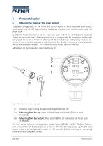
Measuring span at the level sensor To enable configuration of the 4 mA and 20 mA points at the CONDURIX level sensor, two buttons and an LED (light emitting diode) are provided near the terminals inside the probe head. By default, the level sensor is set to maximum span with 4 mA at the probe base and 20 mA at the sensor head. The measuring span is configurable for adaptation to the tank concerned. However, a minimum distance of 10 mm between both points must be observed. If this minimum distance is not observed, the display direction of the level sensor will be reversed automatically. The...
Open the catalog to page 12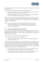
In configuration mode, the 4 mA or 20 mA point, or both reference points, can be modified in any order. To define a reference point while the sensor is in configuration mode • briefly (1-2 seconds) press “4 mA” button (2) to define a current consumption of 4 mA for the present immersed position of the sensor. briefly (1-2 seconds) press “20 mA” button (3) to define a current consumption of 20 mA for the present immersed position of the sensor. When the “4 mA” button is pressed, the LED goes out for 5 seconds. When the “20 mA” button is pressed, the LED lights up permanently for 5 seconds....
Open the catalog to page 13All FAFNIR catalogs and technical brochures
-
TORRIX M12 MOBILE
2 Pages
-
TORRIX XTS
2 Pages
-
TORRIX 6
1 Pages
-
LPG Sensors
8 Pages
-
SEPARIX
8 Pages
-
Process Automation
28 Pages
-
O²-PID
4 Pages
-
COMS Leaflet
4 Pages
-
VAPORIX Flow and Control
40 Pages
-
Wallmounting Typ 907
4 Pages
-
QE 200
4 Pages
-
UM 2.1/2.2/2.3
20 Pages
-
TORRIX HART
28 Pages
-
TORRIX RS485 Modbus
16 Pages
-
TORRIX M12
40 Pages
-
FAFNIR Hart Setup
9 Pages
-
LS 300 / 500
7 Pages
-
76 A / NB 220
5 Pages
-
76 / NB 220
2 Pages
-
SECON-X
4 Pages
-
PRESSURIX
12 Pages
-
Insite360
4 Pages
-
Plugs
12 Pages
-
UM 2.1/UM 2.2/UM 2.3
20 Pages
-
TORRIX-HART
28 Pages
-
DIVELIX
8 Pages
-
CONDURIX-HART
28 Pages
-
VAPORIX
12 Pages
-
VISY-X
24 Pages
-
Accessories
3 Pages
-
VISY-Command Web
4 Pages
-
VISY-Reed
4 Pages
-
VISY-RF
2 Pages
-
VISY-Stick
15 Pages
-
VISY-TD Display
2 Pages
-
VISY-View Touch
2 Pages
-
VPI - VISY-Power Interface
1 Pages
-
TORRIX
10 Pages
-
TORRIX CI
1 Pages
-
TORRIX RS485
3 Pages
-
UM-X Transducer
3 Pages
-
TEMPERIX
8 Pages
-
HPH Ex d
3 Pages
-
VISY-Monitor
2 Pages
-
VISY-Input VISY-Output
4 Pages
-
VISY-Command
5 Pages
-
LPG-Sensoren
8 Pages
Archived catalogs
-
2019 VISY-Stick Flex
2 Pages
-
2016 VISY-Stick Flex
2 Pages
-
VISY-X LON
10 Pages
-
SEPARIX
23 Pages
-
VAPORIX Flow/Control
32 Pages
-
VISY-Setup V 3.1.0
40 Pages
-
VISY-Setup V2.10
42 Pages
-
VISY-View
24 Pages
-
VISY-Stick and VISY-Command
24 Pages
-
Overfill Prevention (GWG)
12 Pages


