- Catalogs
- FAFNIR GmbH
- VISY-X LON
VISY-X LON
1 /10Pages

VISY-X LON
1 /10Pages
Catalog excerpts
IFSF LON Interface Converter Page 3/10 >
Open the catalog to page 3
Page 4/10 IFSF LON Interface Converter >
Open the catalog to page 4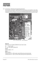
2.4Connection, indicating and operating elementsThe interface converter is delivered from the factory pre-installed in the VISY- Command switch cabinet. Prior to the commissioning procedure, only the LON integration must be made according to the following terminal connection plan. Node-ID Setting the user address (NODE-ID) and reset modeS1:Reset modeS2...S8:user address (Node-ID) > Fig. 2: Connection plan LON integration Power Power supply, + 5 V Reset Reset button Coding switch S1 = ON: master reset (following commissioning) Coding switch S1 = OFF: normal reset (during normal operation) > Page...
Open the catalog to page 6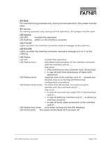
JP2-Boot For manufacturing purposes only; during normal operation, the jumper must be open JP1-Service For testing purposes only; during normal operation, the jumper must be open LED Service LED OFF:trouble-free operation LED flashing:defect on the interface converter LED TX-LON Lights up when the interface converter sends a message via the LON bus. LED RX-LON Lights up when the interface converter receives a message sent to it via the LON bus. LED Status LED OFF:trouble-free operation LED flashes once:disturbed communication of the interface converterwith the interface card VI-..., may occur:...
Open the catalog to page 7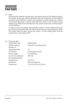
Page 8/10 IFSF LON Interface Converter >
Open the catalog to page 8All FAFNIR GmbH catalogs and technical brochures
 TORRIX M12 MOBILE
2 Pages
 TORRIX XTS
2 Pages
 TORRIX 6
1 Page
 LPG Sensors
8 Pages
 SEPARIX
8 Pages
 Process Automation
28 Pages
 O²-PID
4 Pages
 COMS Leaflet
4 Pages
 VAPORIX Flow and Control
40 Pages
 Wallmounting Typ 907
4 Pages
 QE 200
4 Pages
 76 / NB 220
2 Pages
 UM 2.1/2.2/2.3
20 Pages
 TORRIX HART
28 Pages
 TORRIX RS485 Modbus
16 Pages
 TORRIX M12
40 Pages
 FAFNIR Hart Setup
9 Pages
 LS 300 / 500
7 Pages
 76 A / NB 220
5 Pages
 SECON-X
4 Pages
 PRESSURIX
12 Pages
 Insite360
4 Pages
 Plugs
Plugs12 Pages
 UM 2.1/UM 2.2/UM 2.3
20 Pages
 TORRIX-HART
28 Pages
 DIVELIX
8 Pages
 CONDURIX-HART
28 Pages
 CONDURIX
24 Pages
 VAPORIX
12 Pages
 VISY-X
24 Pages
 Accessories
3 Pages
 VISY-Command Web
4 Pages
 VISY-Reed
4 Pages
 VISY-RF
2 Pages
 VISY-Stick
15 Pages
 VISY-TD Display
2 Pages
 VISY-View Touch
2 Pages
 TORRIX
10 Pages
 TORRIX CI
1 Page
 TORRIX RS485
3 Pages
 UM-X Transducer
3 Pages
 TEMPERIX
8 Pages
 VISY-Input VISY-Output
4 Pages
 VISY-Command
5 Pages
 LPG-Sensoren
8 Pages


Archived catalogs
 HPH Ex d
3 Pages
 VISY-Monitor
2 Pages
 2019 VISY-Stick Flex
2 Pages
 2016 VISY-Stick Flex
2 Pages
 SEPARIX
23 Pages
 VAPORIX Flow/Control
32 Pages
 VISY-Setup V 3.1.0
40 Pages
 VISY-Setup V2.10
42 Pages
 VISY-View
24 Pages
 VISY-Stick and VISY-Command
24 Pages
 Overfill Prevention (GWG)
12 Pages


- Liebherr display
- Liebherr temperature sensor
- LCD display panel
- Industrial display panel
- Liebherr level switch
- Liebherr liquid level switch
- Liebherr level sensor
- Liebherr liquid level sensor
- Analog I/O
- Round plug
- Liebherr interface software
- Liebherr thermocouple
- Liebherr analog level sensor
- Control display system
- Liebherr automatic testing device
- Liebherr stainless steel level switch
- Liebherr leak detector
- Network software
- Liebherr digital output level sensor
- Information display