
- Catalogs
- FAFNIR GmbH
- VISY-Setup V2.10


VISY-Setup V2.10

VISY-Setup V2.10
The VISY-Setup V2.10 GB is a configuration program designed for the VISY-X system, primarily used at filling stations to measure tank levels, product temperature, and water levels. It supports up to 16 tanks and includes components such as VISY-Stick probes and VISY-Command control units. The software operates on a PC and connects to the control unit via a serial interface.
The software requires an IBM-compatible computer with a minimum of a 486 processor, 33 MHz, 8 MB RAM, Windows 9x/ME/NT, a floppy or CD-ROM drive, 10 MB of hard disk space, a free serial interface, a VGA board, and a colored monitor.
To install VISY-Setup, any previous versions must be uninstalled. Installation is performed from a disk or CD-ROM by executing Setup.exe and following the on-screen instructions.
The software is menu-driven, allowing users to navigate through submenus and functions using screen buttons or function keys. Unsupported functions are displayed in grey.
Configuration involves setting up the VISY-Command control unit, which requires connection to the PC. This includes selecting the host computer, setting date and time, and verifying probe connections. Configuration data includes control unit version, minimum software version, host computer selection, and date/time settings.
The document provides guidance on interpreting status and error messages during the configuration process.
The annex includes a menu plan and an index of the VISY-Setup version, detailing program functions.
1. Configuration Data Requirements:
- Serial Number: Essential for probe recognition.
- Fixed Offset: Height difference between tank bottom and probe tube end.
- Type of Product: Mandatory due to density differences.
- Product Designation: Optional display name.
- Product Code: Required by some host computers.
- Alarm Configuration: Set up to four product and two water alarm values.
Access the 'Probes' menu, select the tank number, and enter required data. Set alarm values and repeat for all tanks.
Used to determine real filling volume by interpolating filling level and volume pairs. Requires at least 10 elements.
Default reference temperature is 15°C. Permissible filling rate is set as a percentage for overfill prevention.
Manual entry requires tank dimensions and volume information. Automatic calculation may lack accuracy.
Displays product level, water level, product temperature, real filling volume, and more.
- Displaying Measuring Values: View tank data by entering the tank number.
- Saving Configuration: Save configuration data for backup.
- Loading Configuration: Reload stored configurations to the control unit.
Catalog excerpts

The configuration programm VISY-Setup is part of the VISY-Xsystem ( V olume I nformation S ysyem). The VISY-X system isapplied at filling stations for the accurate and continuous measuring of filling levels of up to 16 tanks. The product temperature and the water level on the tank bottom are measured simultaneously. The system consists of one to eight or one to sixteen probes VISY-Stick, the control unit VISY- Command 8 or VISY-Command 16, and the configuration software VISY-Setup.All data parameters measured by the probe VISY-Stick are setand entered by means of the configuration software VISY-Setup,...
Open the catalog to page 4
Helpful information that should be observed is indicated by italic characters and the left-hand symbol. >
Open the catalog to page 5
If an older version of VISY-Setup is already installed onyour computer, it is advisable to uninstall this program first. In the system control menu, select the item Soft- wareē and then VISY-Setupē from the list of installed programs. Click Removeē and continue by following the instructions on the screen. Installing from a Disk 1. Exit all Windows applications.2. Insert disk 1 into the disk drive.3. In Windows Explorer, change to the disk drive (usually A:\ē).4. Use a double-click to start the Setup.exe program.5. Follow the instructions on the screen. Installing from a CD-ROM 1. Exit all Windows...
Open the catalog to page 6
The VISY-Setup program can be operated by means of themouse or, should you work with a Notebook without mouse connection, by means of the keyboard.This manual describes the operation by means of the mouse.Keys available for required functions are indicated in the VISY-Setup menu. If this is not the case, or if there are otherpossibilities of operation, this is mentioned accordingly. Key designations are indicated by angular brackets.Example: Key [ ] (Return).Messages that must be confirmed by clicking the screen buttonOKԓ are confirmed via the keyboard by pressing key [ ](Return) or key [ENTER].An...
Open the catalog to page 8
The configuration of the control unit VISY-Command must beperformed in the order described in this chapter.All values entered or modified by you are transferredimmediately to the control unit accompanied by the message Values have been saved!ԓ. The exceptions are the tank contents tables, which are only transferred after completion by means of an explicit command. > Before configuring the control unit VISY-Command it must be installed (connection of VISY-Sticks and power supply) and connected to the PC or Notebook via a serial interface cable (COM1 or COM2) (see Application of System VISY-X....
Open the catalog to page 9
2.The main menu is displayed. > To exit the program, in the main menu click the screen buttonExit (ESC)Ԕ. > VISY-Setup V2.10 GB 11 size="-1">
Open the catalog to page 11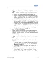
If you have connected VISY-Setup to a VISY-Commandcontrol unit of a lower version than 1.04, the screen displays a selection list of the supported host computers. > The indicated time and date are read into the control unit only when the window is opened and are not continuously updated. >
Open the catalog to page 13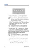
The control unit VISY-Command supports the automatic changeover to European summer time or winter time (on the last Sunday in March or October respectively). This function is activated or deactivated using the checkbox in this window. Default: activated > In case of an incorrect entry (e.g. February 30th), the message that the values have not been saved will be displayed on the screen. > . This function is only supported by interface cards of the type VI-2 and higher as well as by probes as from serial number 1000. Probes below this serial number are not recognised >
Open the catalog to page 14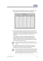
If no functional probe is found at one or several of the connections, the corresponding line in the table will remain empty. > Prior to the above-described transfer of the serial numbers into the control unit, it is important to make sure that the connecting cables are not mixed up and that the probes found are indeed wired up to the connection of the control unit that corresponds to the desired tank number. > VISY-Setup V2.10 GB 15 >
Open the catalog to page 15
In case of direct transfer of the probe serial numbers into the control unit, the configuration step Input of serial numberē in the next section Configuration Data of the Probeē of this chapter can then be left out. 16 > VISY-Setup V2.10 GB size="-1">
Open the catalog to page 16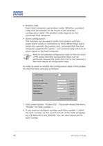
Product codeSome host computers use product codes. Whether a product code must be entered can be found in the attached configuration table. The product codes depend on the connected host computer.ՕAlarm configurationThis function can be used to enter four product and two water alarm values in millimetres or litres. When these alarm values are reached, the control unit provided that the host computer supports this option ֖ will automatically transmit an alarm signal to the host computer. > Refer to the attached configuration table to find out which of the below described configuration steps must...
Open the catalog to page 18
3.The input of the serial number of the probe is mandatory forthe configuration of the measuring data analysis. Click Change (F2)Ԕ.4.Enter the serial number of the probe (max. 5 digits) via thekeyboard. Click OKԔ. The display briefly shows the message Values have been saved!ԓ and returns to the menu window ProbesԔ.5.Click Change (F3)Ԕ, in order to enter the fixed offset of theprobe.6Enter the height of the offset in mm (max. 3 digits), and clickOKԔ. The display briefly shows the message Values have been saved!ԓ and returns to the menu window ProbesԔ.7.Now select the type of product filled into...
Open the catalog to page 19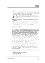
14.Use the arrow button to select the unit (mm or l). Then enterthe alarm values and click OKē. On the screen, the message Values have been saved!ē will be displayed for a short time and then the menu window Probesē again. > Alarm values entered in litres are analysed only if the control unit contains a tank table for the corresponding tank. 15.Repeat the steps 2 to 14 for all tanks connected to the VISY-X system.16.After entering the configuration data for all tanks of theVISY-X- system, click function Back to main menu (ESC)Ԕ. The display returns to the main menu (see page 11). > The tank contents...
Open the catalog to page 21All FAFNIR GmbH catalogs and technical brochures
 TORRIX M12 MOBILE
2 Pages
 TORRIX XTS
2 Pages
 TORRIX 6
1 Page
 LPG Sensors
8 Pages
 SEPARIX
8 Pages
 Process Automation
28 Pages
 O²-PID
4 Pages
 VAPORIX Flow and Control
40 Pages
 Wallmounting Typ 907
4 Pages
 QE 200
4 Pages
 UM 2.1/2.2/2.3
20 Pages
 TORRIX HART
28 Pages
 TORRIX RS485 Modbus
16 Pages
 TORRIX M12
40 Pages
 LS 300 / 500
7 Pages
 76 A / NB 220
5 Pages
 SECON-X
4 Pages
 PRESSURIX
12 Pages
 Insite360
4 Pages
 Plugs
Plugs12 Pages
 UM 2.1/UM 2.2/UM 2.3
20 Pages
 TORRIX-HART
28 Pages
 DIVELIX
8 Pages
 CONDURIX-HART
28 Pages
 CONDURIX
24 Pages
 VAPORIX
12 Pages
 VISY-X
24 Pages
 Accessories
3 Pages
 VISY-Command Web
4 Pages
 VISY-Reed
4 Pages
 VISY-RF
2 Pages
 VISY-Stick
15 Pages
 VISY-TD Display
2 Pages
 VISY-View Touch
2 Pages
 TORRIX
10 Pages
 TORRIX CI
1 Page
 TORRIX RS485
3 Pages
 UM-X Transducer
3 Pages
 TEMPERIX
8 Pages
 VISY-Input VISY-Output
4 Pages
 VISY-Command
5 Pages
 LPG-Sensoren
8 Pages


Archived catalogs
 76 / NB 220
2 Pages
 FAFNIR Hart Setup
9 Pages
 COMS Leaflet
4 Pages
 HPH Ex d
3 Pages
 VISY-Monitor
2 Pages
 2019 VISY-Stick Flex
2 Pages
 2016 VISY-Stick Flex
2 Pages
 VISY-X LON
10 Pages
 SEPARIX
23 Pages
 VAPORIX Flow/Control
32 Pages
 VISY-Setup V 3.1.0
40 Pages
 VISY-View
24 Pages
 VISY-Stick and VISY-Command
24 Pages
 Overfill Prevention (GWG)
12 Pages


- Temperature probe
- LCD display panel
- Industrial display panel
- FAFNIR level switch
- FAFNIR liquid level switch
- FAFNIR level sensor
- FAFNIR liquid level sensor
- Analog I/O
- Round plug
- Interface software
- Thermocouple temperature transducer
- Float level switch
- FAFNIR analog level sensor
- Control display system
- Automatic test kit
- Stainless steel level detector
- Leak monitor
- Network software
- Information display