- Catalogs
- FAFNIR GmbH
- VAPORIX Flow/Control
VAPORIX Flow/Control

VAPORIX Flow/Control
The VAPORIX system is an automated monitoring solution for vapour recovery systems at filling stations, compliant with the 21st BImSchV regulation. It can monitor both sides of a dispenser using a single system, featuring VAPORIX-Flow sensors and a VAPORIX-Control evaluation system, with optional components for enhanced functionality.
Safety Instructions
The system is intended solely for measuring vapour flow at filling stations. Unauthorized modifications or use of non-original parts can cause damage. Installation and maintenance should be conducted by qualified personnel, with repairs limited to FAFNIR or authorized companies.
VAPORIX-Flow Sensor
Structure and Function: Utilizes a calorimetric principle to measure vapour flow and concentration, consisting of a measuring pipe with sensors for temperature, flow, and concentration.
Installation: Must be installed vertically in the vapour recovery pipe, adhering to specific pipe length and diameter conditions. Additional measures may be required to mitigate pulsation effects.
Technical Data: Explosion-proof with specific certifications and operating conditions.
VAPORIX-Control Evaluation System
Structure and Function: Processes data from VAPORIX-Flow sensors to determine vapour flow and concentration, comparing these with fuel flow data to assess system status, indicated by a three-color LED.
Status Indicator
Uses a color-coded LED system: Green for normal operation, green and orange flashing for deviations, orange for faults requiring service within 72 hours, and red for critical faults that shut down the dispenser.
Installation Guidelines
Must be installed according to national regulations and safety laws, housed in a casing with IP20 protection, and not installed outdoors. Only certified VAPORIX-Flow sensors should be connected.
Technical Data
Explosion-proof, certified under TÜV 99 ATEX 1508X, operating at temperatures between -30°C and +50°C with a 230 V AC power supply. Includes interfaces such as RS-232 and RS-485 for communication.
Error Prevention and Troubleshooting
Ensure dispenser settings do not exceed maximum fuel pumping rates. The vapour recovery system should be gas-tight and free of leaks. Calibration and simulation measurements are recommended.
Operating Instructions
The VAPORIX-Flow sensor is maintenance-free under normal conditions, monitoring vapour flow using heat abstraction. The VAPORIX-Control system evaluates these measurements and is also maintenance-free, with service involving complete unit replacement if necessary.
Annex
Includes EC declarations of conformity and type-examination certificates for both the VAPORIX-Flow sensor and the VAPORIX-Control system.
Catalog excerpts
The VAPORIX system is used to measure and assess the vapour flow of the vapourrecovery systems at filling stations. Please use the system for this purpose only. The manufacturer will not be liable for any form of damage resulting from improper use!The measuring value sensor and the measurement evaluation system weredeveloped, manufactured and inspected in accordance with state-of-the-art technology and with recognised safety rules and regulations. Nevertheless, hazards may arise from the use of these devices. Therefore, please observe the following safety instructions:Do not make any changes,...
Open the catalog to page 4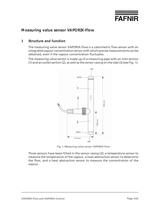
Fig. 1: Measuring value sensor VAPORIX-Flow VAPORIX-Flow and VAPORIX-ControlPage 5/32 >
Open the catalog to page 5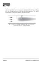
Fig. 2: Function principle of the VAPORIX-Flow: The grey tail representsthe heat abstraction into the flowing medium. VAPORIX-Flow and VAPORIX-ControlPage 6/32 >
Open the catalog to page 6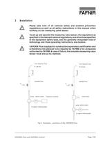
Please take note of all national safety and accident preventionregulations as well as all safety instructions in this manual whenworking on the measuring value sensor. To set up and operate the measuring value sensor, the regulations asspecified in the relevant national regulations, as well as those specifiedin the equipment safety laws, and the generally recognised rules of technology and these operating instructions, are decisive. VAPORIX-Flow is subject to construction supervisory certification andis therefore only allowed to be repaired by FAFNIR or by companiesauthorised by FAFNIR. In case...
Open the catalog to page 7
2.1Installation of the VAPORIX-Flow in the dispenserFor proper assembly of the VAPORIX-Flow, the following installation conditions must be fulfilled (see Fig. 3):The VAPORIX-Flow is fitted in the vapour recovery pipe before the pump andbefore the control valve if one has been fitted.ՕThe unit must be fitted vertically and the inlet section must be at the top. Thedirection of flow has been cast on the casing. The arrow indicating the direction of flow must point from the top tothe bottom. A straight vapour pipe (smooth pipe or corrugated pipe) with a length of atleast 50 mm and an inner diameter...
Open the catalog to page 8
To guarantee the measuring accuracy of the VAPORIX system, the additionalinstallation measures listed below for the vapour recovery system constellations must be carried out:2.2.1Diaphragm or piston pumps with proportional valve controlThe pulsation is shielded to a large extent by the proportional valve. However, a minimum pipe volume of approx. 50 cm > 3 should be provided. This corresponds toa total pipe length of approx. 80 cm between the sensor and vapour pump, with an inner diameter of 9 mm.2.2.2Double piston pumps with speed controlHere a minimum pipe volume of approx. 50 cm > 3 should...
Open the catalog to page 9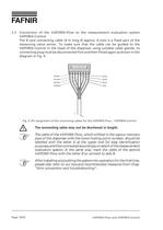
2.3Connection of the VAPORIX-Flow to the measurement evaluation systemVAPORIX-Control The 8 core connecting cable (4 m long approx. 6 mm) is a fixed part of the measuring value sensor. To make sure that the cable can be guided to the VAPORIX-Control in the head of the dispenser using suitable cable glands, its connecting plug must be disconnected first and then fitted again as shown in the diagram in Fig. 4. > Fig. 4: Pin assignment of the connecting cables for the VAPORIX-Flow ؖ VAPORIX-Control The connecting cable may not be shortened in length. The cable of the VAPORIX-Flow, which is fitted...
Open the catalog to page 10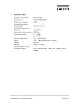
Explosion protection:EEx ia IIB T3Certification:TV 99 ATEX 1509Protection category:IP 65Permissible ambienttemperature:-30 ܰ C to +50 CPermissible operatingpressure:max. ATMMaximum testing pressure:300 kPaConnection data:U > m = 23.9 VI > m = 0.345 AConnecting thread:3/8" inside threadCable:PVC Ж fuel-resistant up to a pointLength:269 mmWeight:approx. 1100 gMaterial of the media-contacting parts:brass, stainless steel 1.4401 and 1.4436, St-zinc-plated > VAPORIX-Flow and VAPORIX-ControlPage 11/32 size="-1">
Open the catalog to page 11
Fig. 5: Measurement evaluation system VAPORIX-Control VAPORIX-Flow and VAPORIX-ControlPage 12/32 >
Open the catalog to page 12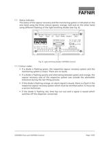
Fig. 6: Light-emitting diodes VAPORIX-Control VAPORIX-Flow and VAPORIX-ControlPage 13/32 >
Open the catalog to page 13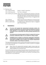
1.1.2Flashing codesLED is flashing slowlySystem is ready for operationLED is flashing quicklyFuel flow is displayed LED is flashing very quicklyVapour flow is displayed even though no fuel flowis present (connections of the measuring value sensor Side A/B have been confused). Please rectify error immediately, otherwise an alarm is triggered after 10 tank fillings.LED is flashingMeasuring value sensor defective or connection fault(ON for a long time,on the plug-in connector. Rectify error immediately OFF for a short time)or replace sensor, otherwise an alarm is triggeredafter 10 tank fillings....
Open the catalog to page 14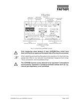
Only measuring value sensors of type VAPORIX-Flow which havebeen certified by an approved European test office may be connected. After installing and putting the system into operation for the first time,please also refer to our tips and recommended measures from Chap."Error prevention and troubleshooting". The VAPORIX-Control is only allowed to be operated in atmosphericenvironments. Operation in pressure-enclosed casings such as, e.g.,natural gas dispensers, is not permitted. > VAPORIX-Flow and VAPORIX-ControlPage 15/32 Fig. 7: Connections VAPORIX-Control size="-1">
Open the catalog to page 15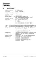
Explosion protection: II G [EEx ia] IIBCertification:TV 99 ATEX 1508XCasing protection type:IP 20Permissible ambienttemperature:-30 ܰ C to +50 CAuxiliary power (L, N, PE):230 V alternating voltage б 10%Max. voltage for safety reasons: U > m = 253 VConnection data perin type of protection [EEx ia] IIBsensor circuit:Max. values for safety reasons:U > m = 23.9V > m = 0.325 Amax. permissible outer inductance: 1.4 mH max. permissible outer capacitance: 0.9 F The intrinsically safe circuits are safely and galvanically separated fromthe supply circuit up to an apex value of the nominal voltage of 375...
Open the catalog to page 16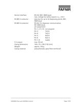
Service interface:RS-232, 8N1, 9600 baud,max. voltage for safety reasons: U > m = 30 VRS-485 2-conductor :data bus for up to 32 dispensing points, 8N1,9600baudRS-485 4-conductor:RS-422, for dispenser communication,8E1,9600baud, pin assignment:Pin 1, 2, 9, 10:not assignedPin 3:TxD BPin 4:TxD APin 5:RxD BPin 6:RxD APin 7, 8:supply5 V output:max. 50 mACasing dimensions:149 x 75 x 100 (110) [mm]Weight:approx. 750 gCasing material:polycarbonate, glass-fibre-reinforced > VAPORIX-Flow and VAPORIX-ControlPage 17/32 size="-1">
Open the catalog to page 17All FAFNIR GmbH catalogs and technical brochures
 TORRIX M12 MOBILE
2 Pages
 TORRIX XTS
2 Pages
 TORRIX 6
1 Page
 LPG Sensors
8 Pages
 SEPARIX
8 Pages
 Process Automation
28 Pages
 O²-PID
4 Pages
 COMS Leaflet
4 Pages
 VAPORIX Flow and Control
40 Pages
 Wallmounting Typ 907
4 Pages
 QE 200
4 Pages
 76 / NB 220
2 Pages
 UM 2.1/2.2/2.3
20 Pages
 TORRIX HART
28 Pages
 TORRIX RS485 Modbus
16 Pages
 TORRIX M12
40 Pages
 FAFNIR Hart Setup
9 Pages
 LS 300 / 500
7 Pages
 76 A / NB 220
5 Pages
 SECON-X
4 Pages
 PRESSURIX
12 Pages
 Insite360
4 Pages
 Plugs
Plugs12 Pages
 UM 2.1/UM 2.2/UM 2.3
20 Pages
 TORRIX-HART
28 Pages
 DIVELIX
8 Pages
 CONDURIX-HART
28 Pages
 CONDURIX
24 Pages
 VAPORIX
12 Pages
 VISY-X
24 Pages
 Accessories
3 Pages
 VISY-Command Web
4 Pages
 VISY-Reed
4 Pages
 VISY-RF
2 Pages
 VISY-Stick
15 Pages
 VISY-TD Display
2 Pages
 VISY-View Touch
2 Pages
 TORRIX
10 Pages
 TORRIX CI
1 Page
 TORRIX RS485
3 Pages
 UM-X Transducer
3 Pages
 TEMPERIX
8 Pages
 VISY-Input VISY-Output
4 Pages
 VISY-Command
5 Pages
 LPG-Sensoren
8 Pages


Archived catalogs
 HPH Ex d
3 Pages
 VISY-Monitor
2 Pages
 2019 VISY-Stick Flex
2 Pages
 2016 VISY-Stick Flex
2 Pages
 VISY-X LON
10 Pages
 SEPARIX
23 Pages
 VISY-Setup V 3.1.0
40 Pages
 VISY-Setup V2.10
42 Pages
 VISY-View
24 Pages
 VISY-Stick and VISY-Command
24 Pages
 Overfill Prevention (GWG)
12 Pages


- Liebherr display
- Liebherr temperature sensor
- LCD display panel
- Industrial display panel
- Liebherr level switch
- Liebherr liquid level switch
- Liebherr level sensor
- Liebherr liquid level sensor
- Analog I/O
- Round plug
- Liebherr interface software
- Liebherr thermocouple
- Liebherr analog level sensor
- Control display system
- Liebherr automatic testing device
- Liebherr stainless steel level switch
- Liebherr leak detector
- Network software
- Liebherr digital output level sensor
- Information display