
- Catalogs
- FAFNIR GmbH
- TORRIX-HART


TORRIX-HART

TORRIX-HART
The document details the TORRIX Field Device with HART Protocol, emphasizing its use in processes and compatibility with HART-capable host devices. It assumes the reader is familiar with HART Protocol requirements and terminology.
The TORRIX level sensor is designed for high-precision liquid level measurement in tanks using magnetostriction. It outputs signals in the 4 to 20 mA range and is available in lengths from 200 to 6,000 mm. It can be installed in explosive atmospheres and comes in versions for bypass installation, flange, or screw-in unit. The HART variant can measure three process values with two floats.
The sensor is identified by its manufacturer (FAFNIR GmbH), model name, device type code, and HART Protocol Revision 6. It supports 1 to 3 device variables and operates as a 2-wire transmitter.
Universal Commands: Read unique identifiers, primary variables, loop current, and write tags and descriptors.
Common Practice Commands: Read device variables, perform self-tests, and reset configurations. Command #72 (Squawk) flashes an LED for identification, and Command #73 (Find Device) requires prior arming.
Device Specific Commands: Write protection modes, read diagnostics, and restore factory defaults.
Device Variable 0: Measures total level with float 1.
Device Variable 1: Measures interface level with float 2.
Device Variable 3: Calculates interface layer thickness using floats 1 and 2.
The device supports four dynamic variables (PV, SV, TV, QV) that can be mapped from device variables using specific commands.
Includes field device status, extended device status, and additional device status, detailing various operational states and error conditions.
Details on power-up, device reset, self-test, sampling rate, and command response delay are provided to ensure optimal performance and reliability.
Guidelines for wiring, installation, and network configuration are provided to ensure proper device operation.
Instructions for configuring the device using various tools like FAFNIR HART-Setup, Emerson 375 Field Communicator, and others are included.
Includes unit conversion tables, damping values, and annexes with capability checklists and default configurations.
Non-Primary Variable Out Of Limits is triggered when a variable exceeds sensor limits. Device Malfunction is indicated by a self-test detecting serious issues, setting corresponding status bits. Extended Device Status includes alerts for variables out of limits or with non-GOOD status.
Errors include HART Parameter Error, Transmitter Parameter Error, Measurement Error, Error Counter Error, and Low Voltage Error. Unused bits are set to zero.
The device has one analogue output, corresponding to the Primary Variable. It supports HART Rev. 6 communication. The output current ranges from 3.8 mA to 20.5 mA, with malfunction indications at 3.6 mA or 21.5 mA. The device requires a minimum of 10 V to operate.
At power-up, configuration data is loaded and checked. If errors are detected, the output is set to an alarm current. Self-tests are conducted at power-up and during operation. Configuration data is stored in non-volatile memory, with write protection available.
For HART installations, shielded twisted pair cables are recommended. Devices on a HART network should conform to HART standards to avoid communication issues.
Various tools like FAFNIR HART-Setup, Emerson 375 Field Communicator, and others are available for configuring TORRIX devices. These tools support most configuration functions, although some limitations exist.
Some configurations can be done using the Local Panel, such as setting range values and alarm current. However, certain commands can restrict these changes.
The device supports multiple engineering units, with conversions handled internally. Damping values can be set for different device variables, with specific options available for each.
Overview of the capabilities of the TORRIX-HART device, including manufacturer, model, revision, device type, HART revision, number of sensors, host side signals, device variables, dynamic variables, common practice commands, device specific commands, additional device status bits, alternative operating modes, burst mode, and write protection.
Details the default configuration settings for the TORRIX device upon leaving the factory, including polling address, number of request and response preambles, configuration change counter, PV upper and lower range values, PV damping, PV engineering units, final assembly number, sensor serial number, tag, long tag, descriptor, date, message, primary and secondary master device lock, write protection, and password. Default configuration of dynamic variables is also provided.
FAFNIR GmbH, Schnackenburgallee 149 c, 22525 Hamburg, Germany. Tel.: +49 / 40 / 39 82 07–0, Fax: +49 / 40 / 390 63 39, E-mail: [email protected], Web: www.fafnir.com
Catalog excerpts
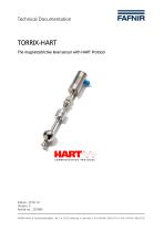
Technical Documentation
Open the catalog to page 1
Page 2/27 TORRIX with HART protocol
Open the catalog to page 2
© Copyright: Reproduction and translation only with the written consent of the FAFNIR company. FAFNIR reserves the right to make product modifications without prior notice. HART® is a registered trademark of the HART Communication Foundation. TORRIX with HART protocol
Open the catalog to page 3
This specification is designed to complement other TORRIX documents (e.g. TORRIX Technical Documentation). It provides a complete description of the TORRIX Field Device from a HART Communication point of view. The FAFNIR GmbH magnetostrictive sensor TORRIX complies with the HART Protocol Revision 6. This document describes all the device specific features and documents HART Protocol implementation details. The functionality of the TORRIX is described in a way that allows its proper application in a process and its complete support in HART capable Host Devices. This document assumes the reader...
Open the catalog to page 4
The high-precision and robust TORRIX level sensor is designed to provide continuous gauging of liquid media levels in tanks. The measuring principle used by the sensor exploits the physical effect of magnetostriction and is largely unaffected by temperature. Magnetostriction is particularly ideal where level measurements are required to be extremely accurate, e.g. in the chemical industry. The level sensor outputs measuring signals in the range 4 to 20 mA. Available in lengths of 200 to 6,000 mm, it is compatible with a variety of tank dimensions. It also comes in the following versions: • Version for...
Open the catalog to page 5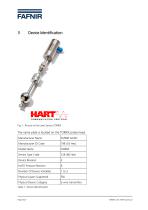
Fig. 1: Picture of the Level Sensor TORRIX The name plate is located on the TORRIX probe head. Table 1: Device Identification Page 6/27 TORRIX with HART protocol
Open the catalog to page 6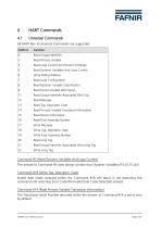
All HART Rev. 6 Universal Commands are supported. CMD Id Function 0 Read Unique Identifier 1 Read Primary Variable 2 Read Loop Current And Percent Of Range 3 Read Dynamic Variables And Loop Current 8 Read Dynamic Variable Classification 9 Read Device Variable With Status 11 Read Unique Identifier Associated With Tag 13 Read Tag, Descriptor, Date 14 Read Primary Variable Transducer Information 15 Read Device Information 16 Read Final Assembly Number 18 Write Tag, Descriptor, Date 19 Write Final Assembly Number 21 Read Unique Identifier...
Open the catalog to page 7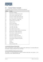
The following Common Practice Commands are supported. CMD Id Function 33 Read Device Variables 34 Write Primary Variable Damping Value 35 Write Primary Variable Range Value 36 Set Primary Variable Upper Range Value 37 Set Primary Variable Lower Range Value 38 Reset Configuration Changed Flag 40 Enter/Exit Fixed Current Mode 41 Perform Self Test 42 Perform Device Reset 44 Write Primary Variable Units 45 Trim Loop Current Zero 46 Trim Loop Current Gain 48 Read Additional Device Status 49 Write Primary Variable Transducer Serial Number 50 Read Dynamic...
Open the catalog to page 8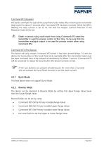
Command #72 (Squawk) The device will flash the LED of the Local Panel (only visible after removing the transmitter head cover) for about 5 seconds after Command #72 has been received. While the LED is flashing the loop current is set to 12 mA and the Output Current Fixed bit in the Response Code will be set. A Death or serious injury could result from using Command #72 when the transmitter is used for process control at that time. So be sure that the transmitters analogue output is not used for process control when using Command #72. Command #73 (Find Device) The device will only answer Command...
Open the catalog to page 9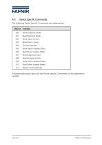
The following Device Specific Commands are implemented: 200 Write Protection Mode 202 Write Alarm Current 203 Read Alarm Current 205 Write Device Variable Offset 206 Read Device Variable Offset 209 Write Device Variable Enable 210 Read Device Variable Enable 211 Restore Factory Defaults A detailed description about all the Device Specific Commands can be obtained on request. Page 10/27 TORRIX with HART protocol
Open the catalog to page 10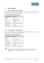
The Device Variable 0 contains the result of the level measurement done with float 1 (upper float). This level represents the total level. Summary of Device Variable 0 properties: * see Section 13.1.1 for additional information. The transmitter is not always equipped with a second float, if there is no second float the measurement data of Device Variable 1 is set to Not-A-Number. TORRIX with HART protocol Page 11/27
Open the catalog to page 11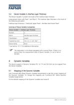
* see Section 13.1.1 for additional information. The transmitter is not always equipped with a second float, if there is no second float the measurement data of Device Variable 3 is set to Not-A-Number. 6 Dynamic Variables The device supports 4 Dynamic Variables (PV, SV, TV and QV) that can be mapped from the Device Variables. 6.1 Mapping of the Dynamic Variables Use Command #50 (Read Dynamic Variable Assignments) to get the current mapping of the Dynamic Variables. To change the mapping use Command #51 (Write Dynamic Variable Assignments). For the default mapping of the Dynamic Variables see...
Open the catalog to page 12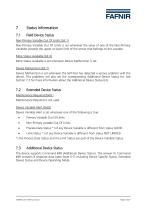
Non-Primary Variable Out Of Limits (bit 1) Non-Primary Variable Out Of Limits is set whenever the value of one of the Non-Primary Variables exceeds the upper or lower limit of the sensor that belongs to this variable. More Status Available (bit 4) More Status Available is set whenever Device Malfunction is set. Device Malfunction (bit 7) Device Malfunction is set whenever the Self-Test has detected a serious problem with the device. This problems will also set the corresponding Additional Device Status bit. See Section 7.3 for more information about the Additional Device Status bits. Maintenance...
Open the catalog to page 13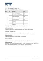
Description of the Device Specific Status bits: * Device Specific Status bits that are not used are set to zero. HART Parameter Error It has been detected that the HART parameters have illegally been changed. Transmitter Parameter Error It has been detected that the transmitter parameters have illegally been changed. Measurement Error It has been detected that a measurement is not possible. Error Counter Error It has been detected that there are to many errors during the measurement. Low Voltage Error It has been detected that the supply voltage is to low. The analogue output has been set to...
Open the catalog to page 14All FAFNIR GmbH catalogs and technical brochures
 TORRIX M12 MOBILE
2 Pages
 TORRIX XTS
2 Pages
 TORRIX 6
1 Page
 LPG Sensors
8 Pages
 SEPARIX
8 Pages
 Process Automation
28 Pages
 O²-PID
4 Pages
 VAPORIX Flow and Control
40 Pages
 Wallmounting Typ 907
4 Pages
 QE 200
4 Pages
 UM 2.1/2.2/2.3
20 Pages
 TORRIX HART
28 Pages
 TORRIX RS485 Modbus
16 Pages
 TORRIX M12
40 Pages
 LS 300 / 500
7 Pages
 76 A / NB 220
5 Pages
 SECON-X
4 Pages
 PRESSURIX
12 Pages
 Insite360
4 Pages
 Plugs
Plugs12 Pages
 UM 2.1/UM 2.2/UM 2.3
20 Pages
 DIVELIX
8 Pages
 CONDURIX-HART
28 Pages
 CONDURIX
24 Pages
 VAPORIX
12 Pages
 VISY-X
24 Pages
 Accessories
3 Pages
 VISY-Command Web
4 Pages
 VISY-Reed
4 Pages
 VISY-RF
2 Pages
 VISY-Stick
15 Pages
 VISY-TD Display
2 Pages
 VISY-View Touch
2 Pages
 TORRIX
10 Pages
 TORRIX CI
1 Page
 TORRIX RS485
3 Pages
 UM-X Transducer
3 Pages
 TEMPERIX
8 Pages
 VISY-Input VISY-Output
4 Pages
 VISY-Command
5 Pages
 LPG-Sensoren
8 Pages


Archived catalogs
 76 / NB 220
2 Pages
 FAFNIR Hart Setup
9 Pages
 COMS Leaflet
4 Pages
 HPH Ex d
3 Pages
 VISY-Monitor
2 Pages
 2019 VISY-Stick Flex
2 Pages
 2016 VISY-Stick Flex
2 Pages
 VISY-X LON
10 Pages
 SEPARIX
23 Pages
 VAPORIX Flow/Control
32 Pages
 VISY-Setup V 3.1.0
40 Pages
 VISY-Setup V2.10
42 Pages
 VISY-View
24 Pages
 VISY-Stick and VISY-Command
24 Pages
 Overfill Prevention (GWG)
12 Pages


- Display module
- Temperature probe
- LCD display panel
- Industrial display panel
- FAFNIR level switch
- FAFNIR liquid level switch
- FAFNIR liquid level sensor
- Analog I/O
- Round plug
- Interface software
- Thermocouple temperature transducer
- Float level switch
- FAFNIR analog level sensor
- Control display system
- Automatic test kit
- Stainless steel level detector
- Leak monitor
- Network software
- Information display