- Catalogs
- FAFNIR GmbH
- SEPARIX
SEPARIX

SEPARIX
The SEPARIX system is an alarm system designed to monitor the thickness of oil or light liquid layers in separators. It consists of sensors (SEPARIX-C H and SEPARIX-C L) and a measuring transducer (SEPARIX-Control C). The system alerts users when the liquid layer exceeds a certain thickness, preventing pollutants from entering sewage systems. Alarms are indicated via LEDs and a buzzer, with options for external alarm connections. SEPARIX-C L is suitable for non-aggressive media, while SEPARIX-C H is designed for aggressive media.
The system should only be used for monitoring light liquid separators. Installation and maintenance must be performed by trained personnel, adhering to safety and explosion protection regulations. SEPARIX-C L is unsuitable for aggressive media, while SEPARIX-C H should not be used with certain chemicals.
Structure and Function: The sensors use a capacitive measuring principle to detect separation layers. SEPARIX-C L has a brass cover for non-aggressive media, while SEPARIX-C H has a stainless steel cover for aggressive media. They trigger alarms when the liquid layer reaches a specific thickness.
Installation: Sensors must be installed by trained personnel, observing safety regulations. They should be positioned to avoid false alarms and can be extended up to 250 meters with appropriate cabling.
Maintenance: Regular cleaning is required to prevent false alarms. Sensors should be tested after cleaning to ensure proper operation.
Technical Data: Includes explosion protection details, dimensions, cable lengths, and operating temperatures.
Structure and Function: This device powers the sensors and analyzes signals. It features LEDs for operation, fault, and alarm indications, and a buzzer for audible alerts. Membrane buttons allow for alarm acknowledgment and system testing.
Options: Custom settings can be configured using jumpers and a switch block to tailor alarm responses.
- Switch 1: Enables automatic alarm repetition after 24 hours if acknowledged (default: no repetition).
- Switch 2: Triggers alarm upon detection of oil/light liquid (default) or water.
- Switch 3: Relay output switches in alarm state (default) or normal mode.
- Switch 4: Alarm can be acknowledged with button (default) or not.
- Installation must be performed by trained personnel following safety regulations.
- Do not install the transducer in explosive zones.
- Wiring should be done with the equipment de-energized.
- Connect the sensor using the specified wiring diagram and observe maximum operating parameters.
- Red LED flashes for alarm; yellow for fault.
- Press Alarm button to acknowledge; LED remains lit until resolved.
- If automatic repetition is enabled, re-acknowledge after 24 hours.
- Explosion protection: II (1) G [EEx ia] IIB/IIC.
- Dimensions: 180 mm x 130 mm x 60 mm; Protection: IP 65.
- Operating temperature: 0 °C to +40 °C; Power: 230 V AC ± 10%.
- Relay output: AC ≤ 250 V, DC ≤ 30 V.
- Detects separation layer between water and light liquid using capacitive principle.
- Available in two versions: SEPARIX-C L (brass cover) and SEPARIX-C H (stainless steel cover).
- Sensor suspended by cable; must be installed below liquid surface at alarm level.
- Regular cleaning required; avoid electrostatic charges.
- Supplies power and analyzes sensor data; indicates alarms via LEDs and buzzer.
- External alarm transmitters can be connected.
- Settings include automatic alarm repetition and detection mode (oil/light liquid or water).
- Auxiliary power: 230 V; 50 – 60 Hz; ±10%.
- Sensor circuit: Voltage ≤ 14.3 V, Current ≤ 21.2 mA.
- Output: Potential-free changeover contact, Urms ≤ 250 V.
Catalog excerpts
The SEPARIX syste m i s an alar m syste m wh i ch m on i tors the th i ckness of the layerof o i l or l i ght l i qu i d occurr i ng i n a l i ght l i qu i d separator (e . g . o i l separator) . A SEPARIX syste m conta i ns the o i l separator sensors SEPARIX-C H or SEPARIX-C Land the m easur i ng transducer SEPARIX-ControlC . The m easur i ng transducer i s connected to an o i l separator sensor and i s des i gnedto supply i t w i th power and to analyse s i gnals . The sensors trans mi t a s i gnal to the connected m easure m ent analys i s un i t i f thelayer of o i l or l i ght l i qu i...
Open the catalog to page 3
The SEPARIX system is designed to monitor the thickness of the layer of lightliquid occurring in light liquid separators. Please use the system for this purpose only. The manufacturer shall not be liable for any form of damage resulting from improper use!The measuring transducer and the oil separator sensors were developed,manufactured and tested in accordance with state-of-the-art technology, and recognized safety rules and regulations. Nevertheless, hazards may arise from the use of the system. Therefore, please observe the following safety instructions:Do not make any changes, add anything...
Open the catalog to page 4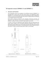
corrugated tube switching point Fig. 1a: Dimensions SEPARIX-CH Fig. 1b: Dimensions ֖ SEPARIX-CL SEPARIX-C and SEPARIX-Control CPage 5/23 >
Open the catalog to page 5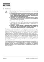
When installing the oil separator sensors, observe the followingsafety instructions:Installation may only be performed by trained personnel observingall the applicable safety regulations. This also applies to the local safety regulations and accident prevention regulations notmentioned in these operating instructions.ՕThe sensors may be installed in the potentially explosive Zone0.Observe all the relevant explosion protection regulations (VDE andall local installation regulations).The sensors must be de-energised.ՕThe sensors must not be used in high-flow, non-conductive liquids(e.g. in pipelines...
Open the catalog to page 6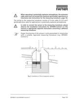
When operating in potentially explosive atmospheres, the extensioncable used must not exceed the maximum permissible capacitance or inductance (see instructions for the measuring transducer, page 10). The wiring to the measuring transducer consists of 3-core cable (3x0.5mm > 2 )(preferably blue cable for applications in potentially explosive atmospheres). In order to connect the sensor to the measuring transducer, pleaseobserve the installation instructions for SEPARIX-ControlC in thismanual or appropriate separate instructions concerning a different measuring transducer. Proper functioning of...
Open the catalog to page 7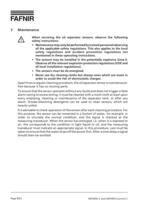
When servicing the oil separator sensors, observe the followingsafety instructions:Maintenance may only be performed by trained personnel observingall the applicable safety regulations. This also applies to the localsafety regulations and accident prevention regulations notmentioned in these operating instructions.ՕThe sensors may be installed in the potentially explosive Zone0.Observe all the relevant explosion protection regulations (VDE and all local installation regulations).The sensors must be de-energised.ՕNever use dry cleaning cloths but always ones which are moist inorder to avoid the...
Open the catalog to page 8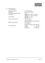
Explosion protection:II1GEExia IIBT5Certificate:TV03ATEX2368XProtection category, housing:IP 68 Dimensions:SEPARIX-CH:28mm x 728mmSEPARIX-CL:28mm x 195mmCable length:SEPARIX-CH:4.5mSEPARIX-CL:5 mAmbient temperature:-20 ܰ C to +70 C-20 а C to +60 C(potentially explosive atmosphere)Medium temperature:0 а C to +70 C0 а C to +60 C(potentially explosive atmosphere)Connection data:Voltage:U > i Тɤ 15VDCCurrent:I > i ≤ 30mAPower input:P > i ≤ 100mW > SEPARIX-C and SEPARIX-Control CPage 9/23 size="-1">
Open the catalog to page 9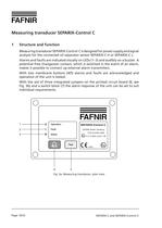
Fig. 3a: Measuring transducer, plan view SEPARIX-C and SEPARIX-Control CPage 10/23 >
Open the catalog to page 10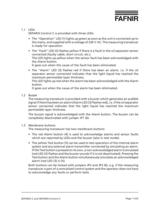
SEPARIX-C and SEPARIX-Control CPage 11/23 >
Open the catalog to page 11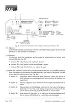
Fig. 3b: Jumpers and switches on the printed circuit board (inside the lid) > SEPARIX-C and SEPARIX-Control CPage 12/23 >
Open the catalog to page 12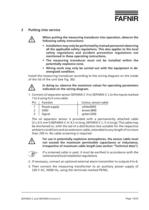
When putting the measuring transducer into operation, observe thefollowing safety instructions:Installation may only be performed by trained personnel observingall the applicable safety regulations. This also applies to the local safety regulations and accident prevention regulations notmentioned in these operating instructions.ՕThe measuring transducer must not be installed within thepotentially explosive zone.Wiring work may only be carried out with the equipment in de-energized condition. Install the measuring transducer according to the wiring diagram on the insideof the lid of the unit (see...
Open the catalog to page 13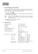
If the o i l separator sensor reports an alar m , the red LED " Alar m" flashes on the m easur i ng transducer . If there i s a fault (fault i n the sensor connected), the yellow " Fault " LED flashes . In such a case, proceed as follows : 1 . Press Alar m button . The yellow/red LED now re m a i ns l i t cont i nuously i nstead of flash i ng; the fault/alar m has been acknowledged . If switch 1 on the "Options" switch block was used to activateautomaticalarm repetition, the alarm will have to be acknowledgedagain 24hours later. 2 . El imi nate the cause of the fault or alar m. The yellow/red...
Open the catalog to page 14
SEPARIX-C and SEPARIX-Control CPage 15/23 >
Open the catalog to page 15
SEPARIX-C and SEPARIX-Control CPage 16/23 >
Open the catalog to page 16
SEPARIX-C and SEPARIX-Control CPage 17/23 >
Open the catalog to page 17
SEPARIX-C and SEPARIX-Control CPage 18/23 >
Open the catalog to page 18
SEPARIX-C and SEPARIX-Control CPage 19/23 >
Open the catalog to page 19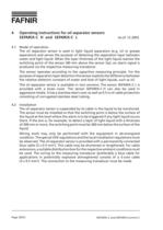
As of: 12.20034.1Mode of operationThe oil separator sensor is used in light liquid separators (e.g. oil or grease separators) and serves the purpose of detecting the separation layer between water and light liquid. When the layer thickness of the light liquid reaches the switching point of the sensor (40 mm above the sensor tip), an alarm signal is produced via the respective measuring transducer.The sensor operates according to the capacitive measuring principle. For thepurpose of separation layer detection this sensor exploits the difference between the relative dielectric constant of water...
Open the catalog to page 20All FAFNIR GmbH catalogs and technical brochures
 TORRIX M12 MOBILE
2 Pages
 TORRIX XTS
2 Pages
 TORRIX 6
1 Page
 LPG Sensors
8 Pages
 SEPARIX
8 Pages
 Process Automation
28 Pages
 O²-PID
4 Pages
 COMS Leaflet
4 Pages
 VAPORIX Flow and Control
40 Pages
 Wallmounting Typ 907
4 Pages
 QE 200
4 Pages
 76 / NB 220
2 Pages
 UM 2.1/2.2/2.3
20 Pages
 TORRIX HART
28 Pages
 TORRIX RS485 Modbus
16 Pages
 TORRIX M12
40 Pages
 FAFNIR Hart Setup
9 Pages
 LS 300 / 500
7 Pages
 76 A / NB 220
5 Pages
 SECON-X
4 Pages
 PRESSURIX
12 Pages
 Insite360
4 Pages
 Plugs
Plugs12 Pages
 UM 2.1/UM 2.2/UM 2.3
20 Pages
 TORRIX-HART
28 Pages
 DIVELIX
8 Pages
 CONDURIX-HART
28 Pages
 CONDURIX
24 Pages
 VAPORIX
12 Pages
 VISY-X
24 Pages
 Accessories
3 Pages
 VISY-Command Web
4 Pages
 VISY-Reed
4 Pages
 VISY-RF
2 Pages
 VISY-Stick
15 Pages
 VISY-TD Display
2 Pages
 VISY-View Touch
2 Pages
 TORRIX
10 Pages
 TORRIX CI
1 Page
 TORRIX RS485
3 Pages
 UM-X Transducer
3 Pages
 TEMPERIX
8 Pages
 VISY-Input VISY-Output
4 Pages
 VISY-Command
5 Pages
 LPG-Sensoren
8 Pages


Archived catalogs
 HPH Ex d
3 Pages
 VISY-Monitor
2 Pages
 2019 VISY-Stick Flex
2 Pages
 2016 VISY-Stick Flex
2 Pages
 VISY-X LON
10 Pages
 VAPORIX Flow/Control
32 Pages
 VISY-Setup V 3.1.0
40 Pages
 VISY-Setup V2.10
42 Pages
 VISY-View
24 Pages
 VISY-Stick and VISY-Command
24 Pages
 Overfill Prevention (GWG)
12 Pages


- Liebherr display
- Liebherr temperature sensor
- LCD display panel
- Industrial display panel
- Liebherr level switch
- Liebherr liquid level switch
- Liebherr level sensor
- Liebherr liquid level sensor
- Analog I/O
- Round plug
- Liebherr interface software
- Liebherr thermocouple
- Liebherr analog level sensor
- Control display system
- Liebherr automatic testing device
- Liebherr stainless steel level switch
- Liebherr leak detector
- Network software
- Liebherr digital output level sensor
- Information display