- Catalogs
- FAFNIR GmbH
- LOF 1.1 and LOF 500/NB 220 Fibre-optical Overfill Protection System
LOF 1.1 and LOF 500/NB 220 Fibre-optical Overfill Protection System

LOF 1.1 and LOF 500/NB 220 Fibre-optical Overfill Protection System
The FAFNIR fibre-optical overfill protection systems, LOF 1.1 and LOF 500/NB 220, are designed to prevent overfilling in storage tanks, especially for water-polluting liquids. These systems are mandatory for tanks exceeding 1,000 liters and include a level detector and a measuring transducer with an alarm unit. A version for hazardous environments (Ex-zone 0) is available.
The system adheres to modern safety standards, requiring specific safety instructions to avoid hazards. Key instructions include using the system only for monitoring liquids, ensuring installation and maintenance by authorized personnel, and regular testing in compliance with local safety regulations.
The system consists of a level detector and a transducer with a binary output. It uses light refraction to detect liquid levels, triggering alarms or control devices as needed.
Installation involves aligning the level detector, adjusting response lengths, and ensuring proper mounting of transducers and overvoltage protection. Specific instructions are provided for different models.
Regular testing is required to ensure functionality, with maintenance performed by skilled personnel.
Guidelines are provided for diagnosing and resolving faults, emphasizing checking connections and signal transmission.
Specifications for level detectors and transducers include probe length, material, and operational temperature ranges.
Contains EC declarations of conformity and type examination certificates, ensuring compliance with safety standards.
Equipped with LEDs, a buzzer, and an acknowledge key for malfunction indication. The alarm activates when liquid levels exceed permissible heights or errors occur.
Follow national safety regulations, ensure wiring is done with equipment disconnected, and use overvoltage protection in explosion hazard areas.
Calculate response length based on tank dimensions, mount perpendicularly, and ensure proper electrical connections.
Install outside explosion hazard areas, adhering to cable length limits and verifying connections before operation.
Install near the level detector if outside buildings.
System requires regular testing, with annual interaction tests to ensure proper operation.
Use the acknowledge button to confirm faults and silence the buzzer, contacting specialists for unresolved issues.
Level detectors operate within -25 °C to +60 °C, with specific power and signal circuit specifications for transducers.
Various versions of level detectors are available for different environmental conditions and installation requirements.
Outlines type codes for level detectors with different probe tube dimensions and coatings, suitable for flammable liquids and specific temperature and pressure ranges.
Level detectors are made from materials like stainless steel, aluminium oxide, and FFKM perfluoroelastomer.
Must comply with technical safety regulations, including the German plant safety directive and VDE regulations.
Specific wiring requirements for overfill prevention sensors, with certified circuits and maximum values outlined.
Includes EC prototype certificate numbers and compliance with EC Guideline 94/9, with specific labelling for certain coatings.
Converts level detector signals into binary outputs, with various types described for specific functionalities.
Electrical data for auxiliary power circuits and level detector circuits are provided, emphasizing compliance with safety regulations.
Catalog excerpts
Overfill Protection System LOF 1.1 and LOF 500/NB220Page 4/43 >
Open the catalog to page 4
The overfill protection system has been developed, manufactured and tested inaccordance with the state of the art and the recognised rules of safety engineering. Nevertheless, it could be hazardous. Therefore, please observe the following safety instructions. > The safety instructions contained in this manual are highlighted as follows: If you fail to observe these safety instructions, there will be a risk ofan accident or the LOF1.1.., LOF500../NB220.. overfill protection system may be damaged. Useful information to ensure that the overfill protection system operatesproperly or make your work...
Open the catalog to page 5
Overfill Protection System LOF 1.1 and LOF 500/NB220Page 6/43 >
Open the catalog to page 6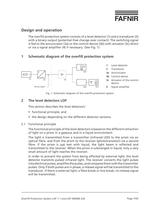
1 Level detector 2 Transducer > Eu 3a Annunciator 3b Control device > (1)(2)(3a)(3b)(3c)Binary signal(4) 3c Actuator of the controldevice 4 Signal amplifier Fig. 1: Schematic diagram of the overfill protection system > Overfill Protection System LOF 1.1 and LOF 500/NB220Page 7/43 >
Open the catalog to page 7
2.2General designThe level detectors consist of a probe tube, which reaches into the tank andcarries a sensor, protected against mechanical damages, on its bottom end. The corresponding probe length is permanently imprinted at the top end of the probe.2.2.1Level detector LOF1.11..This level detector is the LOF standard version and can be used in almost allapplication areas. The transducer electronics are installed in a stainless steel housing located directly on the probe tube (see Fig.2a2d).The level detector can optionally be equipped with an electric plug-in connectionfor a comfortable connection...
Open the catalog to page 13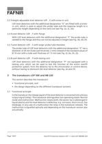
2.2.5Height-adjustable level detector LOF..E with screw-in unitLOF level detectors with the additional designation "E" are fitted with a screw-in unit, which is used to adjust the probe tube and the response length to a particular height depending on the tank size (see Fig.2a, 2c, 2e).2.2.6Level detector LOF..F with flangeWith LOF level detectors with the additional designation "F" the probe tube iswelded to the flange and thus can not be adjusted in height (see Fig.2b, 2d, 2f).2.2.7Level detector LOF..S with larger probe tube diameterThe probe tube of LOF level detectors with the additional...
Open the catalog to page 14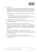
Overfill Protection System LOF 1.1 and LOF 500/NB220Page 15/43 >
Open the catalog to page 15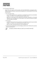
3.2.5Transducer NB220QSApart from the green and the yellow LED the NB220QS is equipped with afurther red lamp, a buzzer, and an acknowledge key for indicating and confirming malfunctions:The red alarm lampՖis lit, if the liquid level has reached or exceeded the maximum permissibleheight, or if there is an overfill protection system error.goes out, if the cause of the malfunctions has been corrected, i.e. the leveldetector has re-emerged out of the liquid or the overfill protection system error has been corrected.֕The buzzersounds, if the liquid level has reached or exceeded the maximum permissibleheight,...
Open the catalog to page 16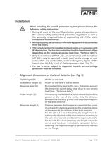
When installing the overfill protection system please observe thefollowing safety instructions:During all work on the overfill protection system always observethe national safety and accident prevention regulations as well asthe generally recognised rules of engineering and all the safetyinstructions in this manual.ՕWiring may only be carried out when the equipment is disconnectedfrom the mains.The transducer must be installed in closed rooms or in a housing withIP 54 protection. The housing protection class for closed rooms differsdepending on the transducer version (see Chap."Technical data").ՕOnly...
Open the catalog to page 17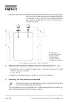
H Tank height S Stub/sleeve height A Response level Z Probe length L Response length Y Reference dimension Fig.3: Alignment dimensions of the level detector > Overfill Protection System LOF 1.1 and LOF 500/NB220Page 18/43 >
Open the catalog to page 18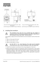
Connectionto transducer Connection to transducer: 1 (brown) + 3 (blue) Fig.4b: Connecting level detector LOF..SteckDD28 plug(counter plug not included in scope of delivery)Fig.4c: Connecting level detector LOF..M12M12 plug(counter plug not included in scope of delivery) The transducer may only be set up outside the area subject toexplosion hazards. The housing protection class differs depending onthe transducer version (see Chap."Technical data"). The length of cable from the level detector to the transducer must not be morethan:250 m in the case of 0.5mm > 2 Օ500 m in the case of 1 mm > 2 750...
Open the catalog to page 20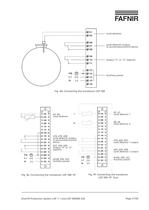
Level detectorLevel detector output,to annunciator/control deviceOutput "S" or "Z" (option)Auxiliary power Fig.4d: Connecting the transducer LOF500 > d2, z2: Level detector 1d8, z8:Level detector 2d18, d20, d22:Level detector 1 outputd24, d26, d28:Level detector 2 outputd/z30, d30, z32:Auxiliary power d2, d4:Level detectord16, d18, d28:Level detector output, to annunciator/control deviced22, d24, d26:Output "S" or "Z" (option)d/z28, d30, d32:Auxiliary power Fig.4f: Connecting the transducerLOF50019"Duo Overfill Protection System LOF 1.1 and LOF 500/NB220Page 21/43Fig.4e: Connecting the transducer...
Open the catalog to page 21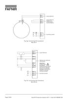
Level detectorLevel detectoroutput, to annunciator/ control device Auxiliary power Level detectorOptions for externalconnection Attention: Outputs are energised! External annunciators and control devices must be connected between terminals 4 and 8 to monitor auxiliary power! Auxiliary power >
Open the catalog to page 22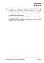
If the level detector is installed in tanks outside buildings, an overvoltageprotection is to be provided in the detector signal line, unless the detector signal line is guided in a metal tube or a metal cable conduit, that is connected to tank potential or integrated into the equipotential bonding system.To install the overvoltage protection:1.Mount the overvoltage protection of type BA350 in a distance of approx.50cmto the level detector.2.Connect the overvoltage protection housing to the tank using a 4-mm > 2 -cableand the external earthing terminal. > Overfill Protection System LOF 1.1 and...
Open the catalog to page 23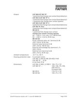
C to +50 а CHousing protection class:In enclosed rooms:LOF500, LS500S/Z, NB 220 H/QS: IP 40 LOF50019"..:IP20 In the field: IP54Dimensions:LOF500, LS500S, LS500Z:150x75x110LOF50019"..:160x100, 7TE, 3HE,DIN41612F, European PCBNB 220 H:110 x 51 x 110 NB 220 QS:150 x 75 x 110 AC: ≤ 250 V, ≤ 4 A, cos ϕ ≤ 0.7, 500 W max.DC: Change-over contact carrying capacity: Pump, solenoid valve, etc. (terminal4, 8): 230 V, 50 Hz, 50 W max. External lamp (terminal5, 8): 230 V, 50 Hz, 100 W max. External acknowledge key (terminal5, 7): 230 V, 50 Hz External horn (terminal9, 8): 230 V, 50 Hz, 50 W max.Ambient temperature:-25...
Open the catalog to page 27All FAFNIR GmbH catalogs and technical brochures
 TORRIX M12 MOBILE
2 Pages
 TORRIX XTS
2 Pages
 TORRIX 6
1 Page
 LPG Sensors
8 Pages
 SEPARIX
8 Pages
 Process Automation
28 Pages
 O²-PID
4 Pages
 COMS Leaflet
4 Pages
 VAPORIX Flow and Control
40 Pages
 Wallmounting Typ 907
4 Pages
 QE 200
4 Pages
 76 / NB 220
2 Pages
 UM 2.1/2.2/2.3
20 Pages
 TORRIX HART
28 Pages
 TORRIX RS485 Modbus
16 Pages
 TORRIX M12
40 Pages
 FAFNIR Hart Setup
9 Pages
 LS 300 / 500
7 Pages
 76 A / NB 220
5 Pages
 SECON-X
4 Pages
 PRESSURIX
12 Pages
 Insite360
4 Pages
 Plugs
Plugs12 Pages
 UM 2.1/UM 2.2/UM 2.3
20 Pages
 TORRIX-HART
28 Pages
 DIVELIX
8 Pages
 CONDURIX-HART
28 Pages
 CONDURIX
24 Pages
 VAPORIX
12 Pages
 VISY-X
24 Pages
 Accessories
3 Pages
 VISY-Command Web
4 Pages
 VISY-Reed
4 Pages
 VISY-RF
2 Pages
 VISY-Stick
15 Pages
 VISY-TD Display
2 Pages
 VISY-View Touch
2 Pages
 TORRIX
10 Pages
 TORRIX CI
1 Page
 TORRIX RS485
3 Pages
 UM-X Transducer
3 Pages
 TEMPERIX
8 Pages
 VISY-Input VISY-Output
4 Pages
 VISY-Command
5 Pages
 LPG-Sensoren
8 Pages


Archived catalogs
 HPH Ex d
3 Pages
 VISY-Monitor
2 Pages
 2019 VISY-Stick Flex
2 Pages
 2016 VISY-Stick Flex
2 Pages
 VISY-X LON
10 Pages
 SEPARIX
23 Pages
 VAPORIX Flow/Control
32 Pages
 VISY-Setup V 3.1.0
40 Pages
 VISY-Setup V2.10
42 Pages
 VISY-View
24 Pages
 VISY-Stick and VISY-Command
24 Pages
 Overfill Prevention (GWG)
12 Pages


- Liebherr display
- Liebherr temperature sensor
- LCD display panel
- Industrial display panel
- Liebherr level switch
- Liebherr liquid level switch
- Liebherr level sensor
- Liebherr liquid level sensor
- Analog I/O
- Round plug
- Liebherr interface software
- Liebherr thermocouple
- Liebherr analog level sensor
- Control display system
- Liebherr automatic testing device
- Liebherr stainless steel level switch
- Liebherr leak detector
- Network software
- Liebherr digital output level sensor
- Information display