
- Catalogs
- FAFNIR GmbH
- CONDURIX


CONDURIX

CONDURIX
The CONDURIX level sensor is designed for continuous measurement of electrically conductive liquids with conductivity greater than 1 μS/cm. It is available in lengths from 200 to 6,000 mm and comes in three models: Mono, DU, and MA. The sensor outputs an analogue value between 4 to 20 mA, with optional HART protocol for digital configuration.
The sensor is exclusively for gauging liquids. Modifications require manufacturer consent. Installation, operation, and maintenance should be performed by qualified personnel, adhering to safety regulations.
The sensor features a screw-in unit or flange for installation, with electrical connections via an M16x1.5 cable gland or M12 plug. It operates by measuring voltage differences along the probe tube to calculate the fill level, requiring a 2-wire 4-20 mA interface with a voltage supply between 8 and 30 V.
Installation must comply with local safety regulations. The sensor can be installed from the top or bottom of the tank. Each model has specific installation requirements: Mono requires a conductive tank surface, DU uses a second rod as a counter electrode, and MA uses a coaxial pipe for shielding and stability.
A two-core unshielded cable is required, ensuring the supply voltage does not drop below 8 V. The sensor head must be protected against water ingress, and proper earthing or equipotential bonding is necessary.
The measuring span is adjustable via buttons and an LED inside the probe head. The default span is set from 4 mA at the probe base to 20 mA at the sensor head. Failure mode current consumption can be set to 21.5 mA or 3.6 mA, following the NAMUR NE43 recommendation.
Regular maintenance includes overhauls and proper handling during return shipments. The sensor should be serviced by qualified personnel to ensure continued functionality.
The sensor operates with a power supply of 8 to 30 V DC and outputs a signal of 4 to 20 mA. It can indicate errors with a current of 3.8 mA or 20.5 mA, and enters failure mode at 3.6 mA. It is designed for use in electrically conductive liquids with a conductivity of at least 1 μS/cm. The sensor head is made of stainless steel with an IP 68 protection rating. The probe tube length ranges from 200 to 6,000 mm, with materials including stainless steel, tantalum, titanium, and Hastelloy.
To adjust current consumption during fault mode, press the "4 mA" button for 3.6 mA or the "20 mA" button for 21.5 mA. The sensor must remain connected to the power supply until it switches from configuration to measuring mode.
The level sensor is maintenance-free. For returns, a Return Material Authorization (RMA) from FAFNIR customer care is required.
The sensor operates within a temperature range of -40 to +125 °C and can withstand a process pressure of 100 bar at 20 °C. It features a digital component with linearity better than ±1 mm or ±1%, and an analogue component with a temperature drift better than ±0.01 %/K.
The CONDURIX Ex series is intrinsically safe and suitable for continuous liquid level measurement. It must be used in compliance with EN 60079-14 and local installation regulations. The sensor is marked with Ex ia IIC/IIB T6 Ga for use in explosive atmospheres.
The sensor is connected via a two-pole electrical connector, and wiring should be performed with the power disconnected. The sensor must be securely attached to the tank, and the installation must comply with EX requirements.
The sensor is marked with the manufacturer's details, type designation, serial number, and certificate number. It is CE marked and has specific electrical data limits for safe operation.
Zone 0 conditions are defined by a temperature range of -20 to +60 °C and a pressure range of 0.8 to 1.1 bar.
Catalog excerpts

Technical Documentation
Open the catalog to page 1
© Copyright: Reproduction and translation are permitted only with the written consent of the FAFNIR GmbH. FAFNIR GmbH reserves the right to make changes to products without prior notice.
Open the catalog to page 3
The purpose of the CONDURIX level sensor is to provide continuous level gauging of electrically conductive liquids (> 1 μS/cm). During the measurement no insulating layer must be formed on the probe tube. The level sensor is available in lengths of 200 to 6,000 mm. With the “single-rod probe” model (CONDURIX Mono), the inside of the container must have a conductive surface (metal containers / downpipes). The “two-rod probe” model (CONDURIX DU) or “jacketed probe” model (CONDURIX MA) are both compatible with non-conductive containers. The standard sensors work by outputting the measured fill level...
Open the catalog to page 4
Safety instructions The purpose of the CONDURIX level sensor is to provide continuous level gauging of liquids. The level sensor must be used exclusively for this purpose. The manufacturer accepts no liability for any form of damage resulting from improper use. The level sensor has been developed, manufactured and tested in accordance with the latest good engineering practices and generally accepted safety standards. Nevertheless, hazards may arise from its use. For this reason, the following safety instructions must be observed: Do not change or modify the level sensor or add any equipment without...
Open the catalog to page 5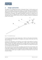
The design of the CONDURIX level sensor is illustrated in Figure 1 with the screw-in unit version as an example. Inside the sensor head (1) of the level sensor and concealed by a cap (2) are the protected terminals and configuration buttons. The electrical connection is established by means of an M16x1.5 screwed cable gland (3) and screw terminals or by an M12 plug-in connection. The potential equalization terminal (4) is required only in conjunction with the CONDURIX Mono version (see section 5 Electrical connection). On the probe neck, there is either a screw-in unit (5) or a flange (not shown)...
Open the catalog to page 6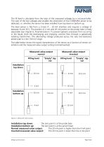
The fill level is calculated from the ratio of the measured voltages by a microcontroller. The ratio of the two voltages also enables the orientation of the CONDURIX sensor to be detected, i.e. whether the sensor has been installed from top down or bottom up. The level sensor is fed from a 2-wire 4 … 20 mA interface and requires a voltage of between 8 and 30 V. The position of 4 mA and 20 mA points on the probe tube is freely adjustable (see chapter 6, Parametrisation). To prevent galvanic processes from occurring in the liquid, both the discharging and charging currents flow through a galvanically...
Open the catalog to page 7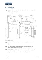
Installation All local safety and accident prevention regulations not expressly referred to herein must be observed. Cable gland M16x1.5 Sensor head Sensor head Probe tube ∅6 Counter electrode ∅ 24 Measuring range Probe tube Flange or screw-in unit R 2 Installation length Jacketed pipe Screw-in unit R ¾ min. or flange Measuring range Connector for equipotential bonding Installation length Connector for equipotential bonding Adjustment range Measuring range Figure 3: CONDURIX variants Level gauging with CONDURIX is possible only in electrically conductive liquids. The level sensor can also be...
Open the catalog to page 8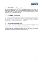
CONDURIX Mono (single rod) With the single-rod probe, the tank acts as the counter electrode. For this reason, the material on the inside of the tank must be conductive and there must be good electrical contact between the tank and the sensor head. For this purpose, the potential equalization terminal must be connected to the tank. With the two-rod probe, the second rod acts as the counter electrode. As the distance from reference potential is constant, the measurement result is unaffected by the geometry of the tank. While the second rod also adds to the stability of the mechanical design, this...
Open the catalog to page 9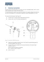
Electrical connection For the wiring of the level sensor, you need a two-core unshielded cable, which is terminated inside the sensor head of the level sensor. It is essential that the correct cross section be selected: the supply voltage at the level sensor must not fall below 8 V in the event of maximum current consumption (21.5 mA). To connect the level sensor (see Figure 4): (1) Unscrew cap (1) using an open-ended spanner (SW 19) Loosen union nut (2) of screwed cable gland (3) Figure 4: Connecting the CONDURIX level sensor Feed two-core cable (4) through union nut (2) and fit screwed cable...
Open the catalog to page 10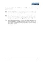
The connector on the underside of the sensor head (5) can be used for earthing or equipotential bonding. With the CONDURIX Mono, the potential equalization terminal (5) must be connected to the electrically conductive tank. Protect the sensor head against the ingress of water. An external cable diameter of 5 to 10 mm ensures reliable sealing of the cable gland. Make sure that the cable gland is screwed tight, and close the cap firmly. During all installation operations, it must be ensured that the negative terminal of CONDURIX is internally connected to the housing. Therefore, use only a galvanic...
Open the catalog to page 11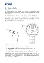
Measuring span at the level sensor To enable configuration of the 4 mA and 20 mA points at the CONDURIX level sensor, two buttons and an LED (light emitting diode) are provided near the terminals inside the probe head. By default, the level sensor is set to maximum span with 4 mA at the probe base and 20 mA at the sensor head. The measuring span is configurable for adaptation to the tank concerned. However, a minimum distance of 10 mm between both points must be observed. If this minimum distance is not observed, the display direction of the level sensor will be reversed automatically. The measured...
Open the catalog to page 12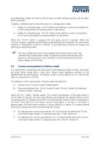
In configuration mode, the 4 mA or 20 mA point, or both reference points, can be modified in any order. To define a reference point while the sensor is in configuration mode • briefly (1-2 seconds) press “4 mA” button (2) to define a current consumption of 4 mA for the present immersed position of the sensor. briefly (1-2 seconds) press “20 mA” button (3) to define a current consumption of 20 mA for the present immersed position of the sensor. When the “4 mA” button is pressed, the LED goes out for 5 seconds. When the “20 mA” button is pressed, the LED lights up permanently for 5 seconds. The...
Open the catalog to page 13All FAFNIR GmbH catalogs and technical brochures
 TORRIX M12 MOBILE
2 Pages
 TORRIX XTS
2 Pages
 TORRIX 6
1 Page
 LPG Sensors
8 Pages
 SEPARIX
8 Pages
 Process Automation
28 Pages
 O²-PID
4 Pages
 VAPORIX Flow and Control
40 Pages
 Wallmounting Typ 907
4 Pages
 QE 200
4 Pages
 UM 2.1/2.2/2.3
20 Pages
 TORRIX HART
28 Pages
 TORRIX RS485 Modbus
16 Pages
 TORRIX M12
40 Pages
 LS 300 / 500
7 Pages
 76 A / NB 220
5 Pages
 SECON-X
4 Pages
 PRESSURIX
12 Pages
 Insite360
4 Pages
 Plugs
Plugs12 Pages
 UM 2.1/UM 2.2/UM 2.3
20 Pages
 TORRIX-HART
28 Pages
 DIVELIX
8 Pages
 CONDURIX-HART
28 Pages
 VAPORIX
12 Pages
 VISY-X
24 Pages
 Accessories
3 Pages
 VISY-Command Web
4 Pages
 VISY-Reed
4 Pages
 VISY-RF
2 Pages
 VISY-Stick
15 Pages
 VISY-TD Display
2 Pages
 VISY-View Touch
2 Pages
 TORRIX
10 Pages
 TORRIX CI
1 Page
 TORRIX RS485
3 Pages
 UM-X Transducer
3 Pages
 TEMPERIX
8 Pages
 VISY-Input VISY-Output
4 Pages
 VISY-Command
5 Pages
 LPG-Sensoren
8 Pages


Archived catalogs
 76 / NB 220
2 Pages
 FAFNIR Hart Setup
9 Pages
 COMS Leaflet
4 Pages
 HPH Ex d
3 Pages
 VISY-Monitor
2 Pages
 2019 VISY-Stick Flex
2 Pages
 2016 VISY-Stick Flex
2 Pages
 VISY-X LON
10 Pages
 SEPARIX
23 Pages
 VAPORIX Flow/Control
32 Pages
 VISY-Setup V 3.1.0
40 Pages
 VISY-Setup V2.10
42 Pages
 VISY-View
24 Pages
 VISY-Stick and VISY-Command
24 Pages
 Overfill Prevention (GWG)
12 Pages


- Temperature probe
- LCD display panel
- Industrial display panel
- FAFNIR level switch
- FAFNIR liquid level switch
- FAFNIR liquid level sensor
- Analog I/O
- Round plug
- Interface software
- Thermocouple temperature transducer
- Float level switch
- FAFNIR analog level sensor
- Control display system
- Automatic test kit
- Stainless steel level detector
- Leak monitor
- Network software
- Information display