Pneumatic Linear Slides

Pneumatic Linear Slides
Fabco-Air provides a range of pneumatic linear slides for various applications. The selection process involves five key factors: bore size, guide shaft diameter, stroke, bearing type and guide shaft material, and slide series selection. Each slide series is detailed with engineering data, order guides, and dimensions.
This series includes construction and engineering data, order guides, tooling and stop options, position sensing options, and dimensions. It is designed for applications requiring adjustable stop collars and bumpers.
Features include construction and engineering data, order guides, dimensions, position sensing options, tooling and stop options, and cushions. This series is suitable for applications needing cushions and specific tooling options.
Includes construction and engineering data, order guides, dimensions, thin parts placer, 3-position tandem cylinder models, adjustable stop options, and position sensing options. It is designed for high-thrust applications with Multi-Power® slides.
Offers construction and engineering data, order guides, dimensions, air cushion, bolt-on options, position sensing options, and rod scraper. It is suitable for applications requiring bolt-on options and rod scrapers.
Includes construction and engineering data, order guides, dimensions, thin parts placer, 3-position tandem cylinder models, adjustable stop options, and position sensing options. It is designed for applications with tooling, stop, and shock options.
Designed for pick and place applications, this series includes construction and engineering data, order guides, position sensing options, tooling, stop and shock options, and dimensions.
Selection involves factors such as bore size, guide shaft diameter, stroke, bearing type, and guide shaft material. Linear ball bearings offer precision, smooth motion, and long life, while sleeve bearings are cost-effective for moderate loads. Material selection for guide shafts is crucial for performance in various environments.
Moisture environments can be managed with Duralon® and pre-chrome stainless steel shafting. Operating speed is a critical factor in slide selection, affecting the life expectancy of bearings and shafts.
The safe speed range for linear slides is generally 6 to 8 inches per second without external stop options. The document explains the impact of acceleration and deceleration on speed calculations, particularly for short strokes, and highlights the potential for severe impact forces at high speeds.
High speeds can be managed with the right combination of bearings, adjustable stops, and shock absorbers. Linear ball bearings are recommended for speeds up to 100 inches per second, except in short stroke, high cycle applications where sleeve bearings may be preferable. The document advises using lubricated air to minimize friction and extend the life of the slides.
To manage impact forces at the end of a stroke, adjustable stops, air cushions, urethane bumpers, or hydraulic shock absorbers are recommended. Hydraulic shocks provide precise end-of-stroke positioning and are suitable for high loads at high speeds.
The document compares various Fabco-Air slide series, including the "TS", "EZ", "L & S", "SE", and "GB" series, highlighting their features, applications, and reasons for selection. Each series offers different configurations of bearings and mounting options to suit specific needs.
A universal sensor system is introduced, compatible with all pneumatic elements in equipment design. The system uses a dovetail style sensor that can be installed on various Fabco-Air products, providing a flexible and easy-to-install solution for position sensing.
The "GB" series slides offer longer strokes, multiple mounting options, and advanced sensor integration. They feature replaceable sleeve bearings and are designed for high load capacity and precision motion.
The document provides guidelines for safe loading, emphasizing the importance of not overloading to prevent reduced product life and accuracy loss. It includes a load sizing guide for the "GB" series, detailing safe loads based on stroke length and deflection limits.
Fabco-Air linear slides are designed for a range of applications, offering various configurations to meet specific operational requirements. The document underscores the importance of proper selection and handling to ensure safe and efficient operation.
The document outlines the specifications for different models of linear slides, including the GB375, GB500, and GB750. Key parameters include guide shaft diameter, bore size, extend and retract power factors, and weight. The stroke lengths vary by model, with options ranging from 1/2 inch to 10 inches.
Several options are available for customization, such as rear clamp bars, tapped guide shafts, Viton seals for higher temperature limits, and magnetic pistons for position sensing. The document also describes the use of proximity switches and magnetic sensors for precise position sensing.
The document details various mounting styles, including thru mounting holes, tapped mounting holes, and side tapped mounting holes. Optional toolbars are available for joining dissimilar slides for X-Y motion, with specific codes for different configurations.
The 'L' & 'S' Series Linear Slides section provides engineering data, including information on magnetic piston bands, end caps, cylinder bodies, and piston rod assemblies. It also covers pre-lubrication, pre-testing, and the use of floating couplers to prevent cylinder rod binding.
The document includes a load sizing guide, specifying maximum loads for fully extended slides and safe loading considerations. It emphasizes the importance of not overloading to prevent reduced product life and potential damage.
This technical document serves as a comprehensive guide for selecting and customizing linear slides, providing detailed specifications, options, and engineering data to ensure optimal performance and application suitability.
The document details the specifications of the "SE" and "EZ" Series Linear Slides. The "SE" series is capable of producing 1,830 pounds of extend force at 100 psi, significantly more than a conventional cylinder. The "EZ" series operates at a maximum pressure of 150 psi and can achieve speeds up to 24 inches per second with optional stop packages.
Models are selected based on guide shaft diameter and stroke length. The "SE" series offers models ranging from SE250 to SE1500, with bore sizes from 1/2" to 3-1/4" and guide shaft diameters from 1/4" to 1-1/2". The "EZ" series includes models from EZ250 to EZ1500, with similar bore and guide shaft specifications.
The slides feature precision adjustment capabilities with fine pitch threads and adjustment nuts. They are constructed with corrosion-resistant materials, including anodized aluminum and blackened steel. The "EZ" series includes linear ball bearings for near play-free operation and precision guide shafts.
Various options are available, including sensor options, shock absorbers, bumpers, and adjustable stops. Integral options include dowel holes, hydraulic seals, and Viton seals. The document also outlines different mounting styles and toolbar options.
Operator safety is enhanced by design features that eliminate pinch points. The document emphasizes the importance of proper model sizing, use of adjustable stops, and operating at the lowest possible air pressure to ensure long product life and prevent failures.
Instructions for ordering include selecting the model size, stroke length, mounting style, and any additional options. The document provides detailed guidance on specifying sensor locations and port configurations.
This document provides detailed specifications and options for the EZP5025 and EZP7550 pick-and-place units. It outlines the steps to select and customize these units based on application requirements, including stroke lengths, mounting styles, and additional options such as sensors and tooling.
The document specifies the guide shaft diameters, bore sizes, and standard stroke lengths for both horizontal and vertical motions. The EZP5025 and EZP7550 models have different configurations, with the EZP5025 offering smaller guide shaft diameters and bore sizes compared to the EZP7550.
The selection process involves choosing the appropriate model size, stroke lengths, and mounting styles. The first two digits of the part number indicate the guide shaft diameter for horizontal motion, while the second pair indicates the diameter for vertical motion.
Various integral options such as Viton seals and toolbar options for mounting grippers are available. The document provides codes for transition plates and toolbars compatible with Fabco-Air "SPG" Series parallel grippers.
Step 2 involves adding sensors, including proximity switches, snap action mechanical switches, and magnetically operated electronic sensors. Specific codes are provided for different sensor types and configurations.
Step 3 allows for the selection of tooling options, adjustable stops, and hydraulic shock absorbers. The document details the available options and their configurations, including standard and alternate shock locations.
The document outlines a three-step process to build a complete model number, incorporating all selected options and configurations. Examples are provided to illustrate the process.
Detailed dimension drawings are included for both the EZP5025 and EZP7550 models, showing mounting styles and optional dowel hole/slot dimensions.
The document emphasizes the importance of selecting the correct options to ensure compatibility and optimal performance. It also notes that specifications are subject to change without notice.
The document provides detailed specifications and options for the 'TS' Series Linear Slides, including sensor types, mounting styles, and additional features such as air cushions and rod scrapers.
The document describes two types of sensors: tie rod mounted sensors (J70-J75) and dovetail style sensors (E70-E77). The sensors are mounted on different surfaces of the cylinder body, with specific codes indicating their location and quantity. Magnetic piston and clamp-on sensors are also available, with options for reed or electronic types.
Various mounting styles are available for horizontal and vertical shafts, including flange mounting styles (MF1 and MF2). The document specifies dimensions and configurations for each mounting style, including options for stop bolts and retainer plates.
The document outlines additional features such as air cushions, which provide controlled deceleration at the end of the stroke, and rod scrapers, which remove contaminants from guide shafts. The air cushion option is available for models TS200 and larger, while rod scrapers are available in metallic or urethane types.
The document provides a detailed guide on how to order the linear slides, including selecting the model size, stroke length, mounting style, and additional options such as sensors and air cushions. Specific codes are used to indicate desired features and configurations.
Detailed dimensional data is provided for each model size, including bore size, guide shaft diameter, and various other measurements critical for installation and operation.
The document serves as a comprehensive guide for selecting and configuring 'TS' Series Linear Slides, offering a wide range of options to meet specific application requirements.
- Retainer Plate: Must be used with the TGS option and one of the accessory blocks (H1, H2, H3, V1, or V2). Specify position as L, R, or B.
- Tooling Mounting Plate: Specify material as Aluminum (A) or Steel (S). Indicate presence of stop bolt with '1' (without) or '2' (with). Options include PL V for vertical mounting blocks and PL H for horizontal mounting blocks.
- ISO 6431 Cylinders: Catalog # FAQR-09
- Manifold Solenoid Valves: Catalog # FVS.Y-09
- Swing Clamps (Pneumatic & Hydraulic): Catalog # FML.H
- Air Pilot & Solenoid Valves: Catalog # FVA.E-09
- Twin Rod, Non-Rotating Air Cylinders: Catalogs # FDF-09 and # FDXS-09
- Multi-Power® Air Presses: Catalog # FP16
- Pancake® II Air Cylinders: Catalog Pan2-2
- Pneumatic Grippers (Parallel Jaw and Angular Motion): Catalog # GR-8
- Stopper Cylinders: Catalog # ST-SC
- Square Pancake® II Air Cylinders: Catalog # SqPan2
- Cylinders, Valves, and Accessories: Catalog # CV9
- NFPA Interchangeable Air Cylinders: Catalog # NF-6
- Global Series™ Metric Air Cylinders: Catalog # GC-15
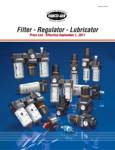
- Modular Air Preparation System - FRLs: Catalog # FRL-06
- ISO 6432 Cylinders: Catalog # FAE-09
- Pneumatic Angular Grippers: Catalog # FKA-09
- Guided Motion Air Cylinders: Catalog # FGM-10
- Air Slide Tables: Catalog # FGXS-10
- Stainless Steel Body Air Cylinders: Catalog # SSB-03
- Fabco-Air, Inc., 3716 N.E. 49th Avenue, Gainesville, FL 32609-1699
- Telephone: (352) 373-3578
- Fax: (352) 375-8024
- Email: [email protected]
- Website: http://www.fabco-air.com
Catalog excerpts

Prices Effective September 1, 2011 Pneumatic Linear Slides
Open the catalog to page 1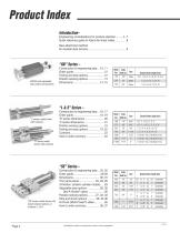
GB750 with adjustable stop collars and bumpers Model Guide Size Shaft Dia. Standard Stroke Lengths (Inch) Standard Stroke Length (Inch) Standard Stroke Length (Inch) “L & S” Series – “L” series model shown with cushions “S” series model shown with cushions “SE” series model shown with dowel hole/slot options on surfaces 2, 3 & 4 Specifications subject to change without notice or incurring obligations Model Guide Size Shaft Dia. 250 375 500 625 by 1/2" increments by 1" increments by 1" increments by 1" increments by 1" increments by 2" increments by 1" increments
Open the catalog to page 2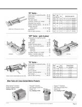
EZ625 with J72B electronic sensors Model Guide Size Shaft Dia. increments increments increments increments increments increments increments increments increments “EZP” Series – (pick & place) Model Size Standard Strokes in 1” Increments Other Fabco-Air Linear Guided Motion Products Global Series® Cylinders Guided Toolplate models Catalog # GC-15 Pancake® Cylinders with External Guide Pins (Option “G”) See Catalog # CV9 Specifications subject to change without notice or incurring obligations Square 1® Cylinders with External Guide Pins (Option “G
Open the catalog to page 3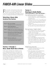
FABCO-AIR Linear Slides abco-Air offers a wide assortment of linear slides, each suited to a vast variety of applications. But how does one know which slide to select? This section of the catalog will guide you through the selection process by providing useful information and helpful hints. Selecting a linear slide involves five factors Factor 1: Bore size of cylinder (determines power factor and linear thrust) Factor 2: Guide Shaft Diameter (determines slide's load capacity) Factor 3: Stroke (select from standard available strokes, or Fabco-Air can provide special stroke lengths) Factor 4: Bearing...
Open the catalog to page 4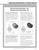
– Engineering Considerations for Product Selection Steel shell linear ball bearings – Yes! Inexpensive linear ball bearings – No! Fabco-Air linear ball bearing slides use high quality, high precision “steel shell” bearings that provide superior load support. Here's why. . With steel shell bearings, the bearing load is distributed back to the housing bore via the entire bearing O.D. The ball bearing's I.D. is unaffected by the housing bore size, therefore providing a very precise “fit” to the guide shaft. Bearing-toshaft pre-load can be accurately established and maintained. Problem: bearing load...
Open the catalog to page 5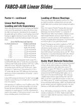
FABCO-AIR Linear Slides Factor 4 – continued Linear Ball Bearing Loading and Life Expectancy Many slide applications involve an overhung load applied to the end of the guide shaft. In almost all of these cases, the slide's load capacity is determined by the strength of the guide shaft and its ability to resist bending. Linear ball bearings are not the limitation because their load capacities dramatically exceed the bending strength of the guide shafts. Linear Ball Bearing Load Capacities For Shaft Diameters of Rolling Load Ratings .250" . . . . . . . . . . . . . . . . 60 lbs each bearing .375"...
Open the catalog to page 6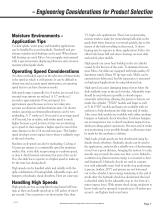
– Engineering Considerations for Product Selection Moisture Environments – Application Tips Coolant splash, water spray, and humidity applications can be handled by several methods. Duralon® and prechrome stainless steel shafting can be used. When linear ball bearings are used, Fabco-Air can supply units greased with a special moisture displacing lubricant and corrosion resistant plated guide shafts. Operating Speed Considerations An often overlooked aspect in the selection of linear slides is the speed at which it will operate. It can be difficult to obtain true and accurate speed information,...
Open the catalog to page 7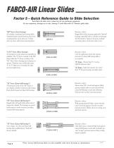
FABCO-AIR Linear Slides Factor 5 – Quick Reference Guide to Slide Selection Each Fabco-Air slide series is shown here for size and layout comparison. For size comparison, drawings are to scale, showing 4" stroke slides with 1/2" diameter guide shafts. “GB” Series (sleeve bearings) Air cylinder is machined into bearing block. Standard features include bottom, side & rear mounting holes, top & side ports. Toolbar with top, front, and bottom mounting holes. “L & S” Series (Sleeve bearings) An inexpensive series using non-repairable air cylinders. The “L” Series is similar to the “EZ” Series while...
Open the catalog to page 8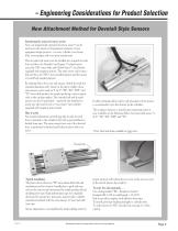
– Engineering Considerations for Product Selection New Attachment Method for Dovetail Style Sensors Introducing the universal sensor system Now, one magnetically operated electronic sensor* can be used across the board on all pneumatic elements of your equipment design projects – on every cylinder, every linear slide, every gripper, and every press requirement. This dovetail style sensor can be installed into integral dovetail slots on Fabco-Air Pancake® and Square 1® cylinder products, plus “GB” series slides and Global Series™ air cylinders equipped with magnetic pistons. The same sensor can...
Open the catalog to page 9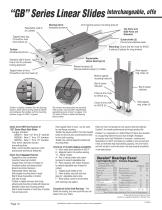
“GB” Series Linear Slides Interchangeable, offe Repairable, built-in air cylinder Bearing blockAnodized aluminum 4mm keyhole sensor mounting slots (2) Top Ports and Side Ports are Standard Tapped holes top, C'bore/thru hole from bottom (2) Guide shafts (2) Pre-chrome stainless steel Mounting: C'bore and thru hole for SHCS 4 places (6 places for long strokes) ToolbarAnodized aluminum Replaceable sleeve bearings (4) Standard slip fit dowel hole & slot for precision tooling alignment Tapped holes at front, C'bore/thru hole from back (4) Retract bumpers (2) Internal extend bumper (1) hidden Rear tapped...
Open the catalog to page 10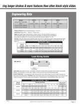
ring longer strokes & more features than other block-style slides Engineering Data Model Guide Shaft Diameter Bore Power Factor Extend Power Factor Retract Pressure Rating: Maximum operating pressure is 150 psi Air Output Force: Output Force = Pressure X Power Factor Speed: Safe speed range is determined by a number of factors. The most important consideration is total reciprocating weight. High loads combined with high speeds can develop severe and damaging impact loads. For speeds over 10 inches per second use extend bumpers (Options "A" or "B"). Accuracy: GB Series Slides feature replaceable,...
Open the catalog to page 11All FABCO-AIR catalogs and technical brochures
 Swing Clamp Cylinders
4 Pages
 PNEUMATIC ROTARY ACTUATORS
8 Pages
 NFPA Air Cylinders
16 Pages
 F-Series Air Cylinders
64 Pages
 Global Series ™ Air Cylinders
48 Pages
 FRB Series Rotary Actuators
8 Pages
 FKHT Series
4 Pages
 FVH-16
1 Page
 H-Series Air Cylinders
32 Pages
 Square 1® Air Cylinders
15 Pages
 Specialty & Control Valves
16 Pages
 FKHQ Gripper
4 Pages
 Hi-Power Cylinder section of CV9
10 Pages
 NFPA Cylinders
8 Pages
 Square 1 Series section of CV9
32 Pages
 FGYB & FGYR Series
12 Pages
 FJU Series Catalog
8 Pages
 FKA Gripper Catalog
4 Pages
 Gripper Catalog
24 Pages
 Pancake® II Catalog
28 Pages
 Air-Oil Tanks
4 Pages
 Multi-Power ® Air Presses
12 Pages
 FKHT Gripper Catalog
4 Pages
 FDH Finger Slide
8 Pages
 FGXS Air Slide Table Catalog
4 Pages
 Master Catalog
200 Pages
 FDF Twin Rod Catalog
4 Pages
 FAE Series ISO-6432 Catalog
12 Pages
 FDXS Twin Rod Catalog
8 Pages
 Square Pancake II Catalog
20 Pages
 Vacuum Generator
1 Page
 Micro-Mist Separator
1 Page




Archived catalogs
 Pneumatic Grippers
24 Pages