Hi-Power Cylinder section of CV9
1 /10Pages

Hi-Power Cylinder section of CV9
1 /10Pages
Catalog excerpts
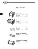
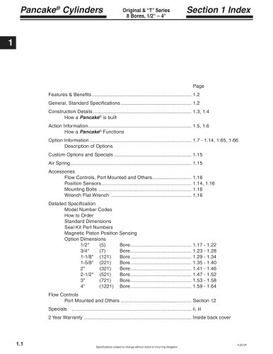
Product Index Hi-Power™ Series – Page Construction & engineering data . . . 4.2 & 4.3 How to Order . . . . . . . . . . . . . . . . . . . . . . 4.4 Dimensions . . . . . . . . . . . . . . . . . . . 4.5 & 4.6 Option Specifications . . . . . . . . . . . 4.7 - 4.10 Multi-Power® Series – Construction & engineering data . . . 5.1 - 5.3 Sizing Guide . . . . . . . . . . . . . . . . . . . . . . 5.2 How to Order . . . . . . . . . . . . . . . . . . . . . . 5.4 Dimensions . . . . . . . . . . . . . . . . . . . 5.5 & 5.6 Option Specifications . . . . . . . . . . . 5.7 - 5.12 Pancake® Multi-Power® Series – Sizing Guide . . . . . . . . . . . . . . . . . . . . . 5.13 How to Order . . . . . . . . . . . . . . . . . . . . . 5.14 Dimensions . . . . . . . . . . . . . . . . . 5.13 & 5.14 Square1® Multi-Power® Series – Sizing Guide . . . . . . . . . . . . . . . . . . . . . 5.18 How to Order . . . . . . . . . . . . . . . . . . . . . 5.18 Dimensions . . . . . . . . . . . . . . . . . . . . . . 5.19 Longstroke™ Multi-Power® Series – Sizing Guide . . . . . . . . . . . . . . . . . . . . . 5.23 How to Order . . . . . . . . . . . . . . . . . . . . . 5.23 Dimensions . . . . . . . . . . . . . . . . . . . . . . 5.24 Specifications subject to change without notice or incur
Open the catalog to page 1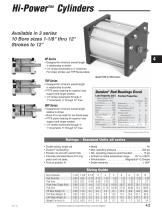
Hi-Power™ CylindersAvailable in 3 10 Bore sizes Strokes to 12 series 1-1/8" thru 12" THP Series • Designed for minimum overall length in relationship to stroke. • PTFE piston bearing for superior load support and longer strokes. • 1/4" stroke increments through 4", 1" increments 5" through 12" max. UHP Series • Designed for minimum overall length relative to stroke. • Buna-N U-cup seals for low break-away. • PTFE piston bearing for superior load support and longer strokes. • 1/4" stroke increments through 4", 1" increments 5" through 12" max. Duralon® Rod Bearings Excel Load Capacity (psi) Machine...
Open the catalog to page 2
Hi-Power™ Cylinders Basic Construction Quick Reference to Components Cylinder OD - is clear anodized aluminum for corrosion resistance and an attractive appearance. The Bore ID is Hard Anodized - Hard anodizing is an electrochemical process which provides a very dense surface of aluminum oxide that actually impregnates the base aluminum. It forms an extremely hard (60 Rc) surface with a low coefficient of friction. Hardness, corrosion resistance and wear resistance exceeds that of chrome plated steel. An Extra Long Rod Bearing - provides long and rigid support for the piston rod. The bearing...
Open the catalog to page 3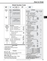
Model Number Code 3 How to Order 1. Specify Series and Bore 2. Specify Stroke in Inches and Fractions 3. Specify Mounting 4. Specify Options Examples HP3 X 3 FF - MR HP Series Hi-Power™, 3" bore, 3" stroke, Front Face (Fabco Pattern) Mount, Male Rod Thread THP5 X 7 RFA - TFR PTFE Piston Bearing Series, 5" Bore, 7" Stroke, Rear Face [NFPA MF2 pattern] Mount, 1/2 NPT Ports in Rod and Cap Heads 1-1/8" thru 6" Bore 8" thru 12" Bore UHP: 1-1/8" thru 12" Bore Hole Thru Double Rod Shaft 150 psi max. operating pressure Nonrotating -K 150 psi max. operating pressure HP: 1-5/8" Bore & Larger THP: All...
Open the catalog to page 4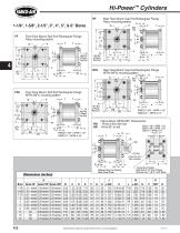
Rear Face Mount; Cap End Rectangular Flange Fabco mounting pattern Front Face Mount; Rod End Rectangular Flange Fabco mounting pattern Q H FABCO 1-5/8" = NFPA 1-1/2" FABCO 3" = NFPA 3-1/4" Clevis Mount (NFPA MP1 Dimensions) - Ports in-line with slot Fabco 1-1/8" = NFPA 1-1/2" -Ports 90° to slot Fabco 1-5/8" = NFPA 1-1/2" A U H FABCO 1-5/8" = NFPA 1-1/2" FABCO 3" = NFPA 3-1/4" Rear Face Mount; Cap End Rectangular Flange NFPA (MF2) mounting pattern Front Face Mount; Rod End Rectangular Flange NFPA (MF1) mounting pattern Q Series HP 1.31 + stroke 1.75 + stroke 2.06 + stroke 2.06 + stroke 2.06 +...
Open the catalog to page 5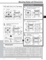
Mounting Styles with Dimensions Mounting Styles with Dimensions 8", 10", and 12" Bores FFA Front Face Mount; Rod End Square Flange NFPA (ME3) mounting pattern Rod End View .1 / K HI"* T T RFA Rear Face Mount; Cap End Square Flange NFPA (ME4) mounting pattern WF Extended Tie Rod Mount, Rod End Only WR Cap End Only To Order Extended Tie Rod Mount Specify Suffix Rod End only WF Dimensions (inches) 1 Cap End View Specifications subject to change without notice or incurring obligation
Open the catalog to page 6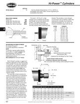
VITON SEALS Hi-Power™ Cylinders OPTION -V Use for elevated temperatures (-15° to + 400°F) or compatibility with exotic media. Consult engineering for compatibility information. MALE ROD THREAD Single Rod -MR For bores 1-1/8" thru 8", a high strength stud is threaded into the standard female rod end and retained with Loctite®. This method eliminates the small diameter thread relief area normally required when machining male threads. This provides a much stronger rod end which can be repaired, rather than replacing the complete rod, should the thread be damaged. For 10" and 12", the thread is...
Open the catalog to page 7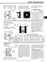
Option Specifications EXTEND PORT BUSHING OPTION 3/8 NPT (2-1/2" - 8" bores) -E38 The cap end plug is replaced with an extended plug of black anodized aluminum with a female NPT port. The standard cap end port is plugged. Use for plumbing convenience, or when higher air flows are required for higher cycle speeds. Dimensions (inches) 1/2 NPT PORTS IN HEADS 2-1/2", 3", 4", 5", & 6" Bores only Rod End Head -TF Both Heads -TFR 3/4 NPT PORTS IN BOTH HEADS 10" & 12" Bores only -P34 For 2-1/2" thru 6" bores thicker heads (to accept 1/2 NPT ports) replace the standard heads. Because of...
Open the catalog to page 8
Hi-Power™ Cylinders (MUM)-MAGNETIC PISTON Option -E Order Sensors and Sensor Clamps Separately • Option-E consists of a magnet bonded into the piston head. When the piston magnet moves past an external sensor, the magnetic field activates the sensor without physical contact. • Mounting - The sensor is attached to a 2-part clamp that attaches rigidly to a tie rod and can be positioned anywhere along the length of the cylinder for very precise signaling. • Two sensor styles are used - (a) the 9-2A197Series for 1-1/8" thru 3" bores requires a tie rod clamp, and (b) the 749Series which accommodates...
Open the catalog to page 9All FABCO-AIR catalogs and technical brochures
 Swing Clamp Cylinders
4 Pages
 PNEUMATIC ROTARY ACTUATORS
8 Pages
 Pneumatic Linear Slides
82 Pages
 NFPA Air Cylinders
16 Pages
 F-Series Air Cylinders
64 Pages
 Global Series ™ Air Cylinders
48 Pages
 FRB Series Rotary Actuators
8 Pages
 FKHT Series
4 Pages
 FVH-16
1 Page
 H-Series Air Cylinders
32 Pages
 Square 1® Air Cylinders
15 Pages
 Specialty & Control Valves
16 Pages
 FKHQ Gripper
4 Pages
 NFPA Cylinders
8 Pages
 Square 1 Series section of CV9
32 Pages
 FGYB & FGYR Series
12 Pages
 FJU Series Catalog
8 Pages
 FKA Gripper Catalog
4 Pages
 Gripper Catalog
24 Pages
 Pancake® II Catalog
28 Pages
 Air-Oil Tanks
4 Pages
 Multi-Power ® Air Presses
12 Pages
 FKHT Gripper Catalog
4 Pages
 FDH Finger Slide
8 Pages
 FGXS Air Slide Table Catalog
4 Pages
 Master Catalog
200 Pages
 FDF Twin Rod Catalog
4 Pages
 FAE Series ISO-6432 Catalog
12 Pages
 FDXS Twin Rod Catalog
8 Pages
 Square Pancake II Catalog
20 Pages
 Vacuum Generator
1 Page
 Micro-Mist Separator
1 Page


Archived catalogs
 Pneumatic Grippers
24 Pages
- Valve
- Industrial press
- Pneumatic valve
- Actuator
- Electrically operated valve
- Vacuum generator
- Forming press
- Vacuum pump
- Linear actuator
- Gas solenoid valve
- NC solenoid valve
- Clamping device
- Single-stage vacuum pump
- Directional control valve
- Double-acting cylinder
- Filter with cartridge
- Hydraulic cylinder
- Gate valve
- Pneumatic cylinder