

VIPER 400

VIPER 400
Catalog excerpts

VIPER 400 These instructions apply to the following model: VIPER 400 electronic appliance LAY-OUT OF VIPER CARD DIS CE DECLARATION OF CONFORMITY Manufacturer: FAAC S.p.A. Address: Via Benini, 1 - 40069 Zola Predosa BOLOGNA - ITALIA - Declares that: The Viper 400 electronic appliance conforms to the essential safety requirements of the following directives: 73/23/EEC and subsequent amendment 93/68/EEC. 89/336/EEC and subsequent amendment 92/31/CEE and 93/68/EEC Additional information: These products underwent tests in a typical, uniform configuration (all products manufactured by FAAC S.p.A.). The Managing Director A. Bassi TABLE 1 VIPER CARD COMPONENTS Introduction: meanings of the following terms as used in these instructions: gateway->the transit area door -> the structure located at the gateway (door, barrier, gate,…) whether automated or not card -> magnetic card or transponder supplied with a code, which is read by an appropriate reader, or a radiocontrol code which is controlled just like a card by means of the connected radio receiver and radio interface. Viper is used for simple control of access, combined with one or more card readers. The card is able to control: • 1 single gateway at entry/exit • 2 separate gateways (one at entry and the other at exit) Only cards and radio codes input in the archive at programming are recognised. TECHNICAL SPECIFICATIONS POWER •Memory capable of recognising a maximum of 400 cards or radio codes •Facility for connecting directly two external readers •Settable control of 1 gateway / 2 gateways •Settable control of electric strike •Settable control of remote control codes •3 displays with 7-segment LEDs for viewing card number and for programming •5 micro-pushbuttons for programming •Inputs: 2 for external readers (Reader A – Reader B) 1 for “door status” microswitch (NO/NC) 1 for door opening push-button (NO) •Outputs: 2 with relay (door-opening Reader A – door-opening Reader B) 1 open-collector (alarm siren) •Power supply: 12Ö24 Vac/dc •Dimensions: 113 x 90 mm •Optional external memory card for archive import/export •Optional external mixer card for connecting two readers to the same Viper input •Optional external radio interface card for managing remote control codes Fuse F1 5x20 400mA/250V delayed LED display Programming micro-pushbuttons A-Reader terminal board (IN-A) B-Reader terminal board (IN-B) Inputs terminal board (INPUT) A-relay output terminal board (OUT-A) B-relay output terminal board (OUT-B) Alarm output terminal board for open collector (ALARM) Power supply terminal board 12V 24Vac/dc (POWER) Connector for external memory card (EXT MEM) To avoid induced noise, separate the card connection cables from any 230V~ power cables and use separate sheaths. To connect the readers (max distance 100m), use a 5x0.5 shielded cable, connecting the shield to the power negative (
Open the catalog to page 1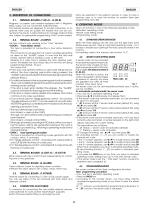
Data are exported to the external memory in order to have a back-up copy or to copy the archive on another Viper (see programming menu #5). Magnetic or passive card readers equipped with a Magnetic Stripe output can be connected indiscriminately. The terminal boards are designed to accept connection of an optional mixer card (to double the readers that can be connected to the input), a radio interface (to manage radiocontrols) and, subject to appropriate programming, FAAC active readers. 4. OPERATING MODES Viper can function in one of the following operating modes: •Standard operating mode •Secret...
Open the catalog to page 2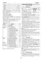
ENGLISH MENU O Column "D" indicates default settings > Procedure for inputting the secret code (if the function was activated): • ''_00‘ is shown; set the 1st secret code number, using ^or^and press OK; • ''_00‘ is shown; set the 2nd secret code number, using ^or^and press OK; • ''_00‘ is shown; set the 3rd secret code number, using ^or^and press OK; If the input code is correct, "_/_" is shown indicating that you have accessed the programming mode, otherwise you return to standard operating mode. > When "_ t_" is shown, Viper is in programming mode and suggests the first of a set of menus. Available...
Open the catalog to page 3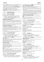
Ģ Use keys éandê to cycle-scan occupied locations only (hold down one or the other to increase scanning speed). The associated location is shown for each location, through the 7 status of the two A and B LEDs in fig.4 (see function “2_7”). Ģ When you have chosen the location, press the CANC key, and the following sequence is shown cyclically: -A only lighted, B only lighted, A+B off, A+B lighted. Ģ Press the OK key to confirm and go on to the next location or press PROG to confirm and return to menu selection. Press éorê not to confirm and go on to the next location. OPERATIONAL SETTINGS To change...
Open the catalog to page 4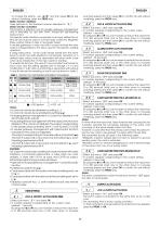
To change the setting , use and then press OK (to exit without modifying, press the PROG key). Radio function disabled: Viper performs in the standard manner described in "S_1" Radio function activated: This function is effective only for double gateway management and is intended for use with FAAC model SLP self-learning radiocontrol. The specific radio interface connected to an input (either IN-A or IN-B will do) must be used to convert radio codes into Magnetic Stripe outputs (Viper is able to recognise these). In double gateways, a valid card will of course activate the relay output corresponding...
Open the catalog to page 5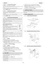
ENGLISH Ģ “__0” steady is shown on the right-hand display. __0 __ Ģ To select the setting use éorê and then press OK. Available associations : 0 “__0” steady = to exit without executing reset (default) “__1” flashing = to execute reset 1 To exit without confirming, press PROG . OUT-B OUTPUT ACTIVATION Ģ Select sub-menu “4_2” and press OK . The OUT-B output is activated for the same time as for a valid card. Ģ The remaining time is shown during activation. To finish activation and exit before the entire time has elapsed, press key PROG or OK ALARM OUTPUT ACTIVATION Ģ Select sub-menu “4_3” and...
Open the catalog to page 6All FAAC SpA catalogs and technical brochures
 Minitime
7 Pages
 Resist T-PS-TPS
1 Page
 TAG - 10
2 Pages
 XTR B
XTR B4 Pages
 S800 ENC
4 Pages
 J SERIES BOLLARD
8 Pages
 Automated system R180
3 Pages
 Parking and access control
15 Pages
 Gearmotor 746 ER
2 Pages
 Operator for swing gatesS418
4 Pages
 Gearmotor C720
4 Pages
 930 AUTOMATIC SLIDING DOOR
6 Pages
 A100 AUTOMATIC DOORS
6 Pages











- Actuator
- Linear actuator
- Electric actuator
- Mechanical lock
- Indoor shutter
- Metal door
- Wireless remote control
- Remote control with buttons
- Door lock
- Fuse box
- Security door
- Light barrier
- Automatic door
- Safety lock
- Stainless keypad
- Exterior door
- Multibeam light curtain
- Stainless steel door
- RFID reader-writer
- Safety light curtain