FELSIC HC
1 /17Pages

FELSIC HC
1 /17Pages
Catalog excerpts

ELECTROLYTIC ALUMINUM CAPACITORS General technical data 1. BASIC CONSTRUCTION Structure of an electrolytic aluminum capacitor is shown hereunder: FELSIC in bank PRORELSIC 125 PRORELSIC 125 SNAPSIC SNAPSIC 105 FELSIC HP BC – BD PRORELSIC 145 CUBISIC PROMISIC 031 CUBISIC LP SNAPSIC 105 LP SNAPSIC 4P SNAPSIC 105 4P SNAPSIC HV SNAPSIC HC SNAPSIC 125 RELSIC 033 CI FRS CI FRS FELSIC 039 (ex 727) FELSIC DI 738 FELSIC 037 (ex 737) 740 FELSIC 125 FRS BC (ex 731) 741 FELSIC 125 FRS BD (ex 731) 742 PRORELSIC 105 TFRS 743 PRORELSIC 105 TFRS 744 FELSIC 85 BC FELSIC 85 LP 745 FELSIC 85 BD 746 FELSIC 85 M BC 747 FELSIC 85 M BD 748 SICAL CO 42 - SICAL 749 SICAL CO 42 - SICAL 750 CUBISIC 125 756 FELSIC 105 BC FELSIC 105 LP 757 FELSIC 105 BD 760 FELSIC HC BC 761 FELSIC HC BD 762 FELSIC 105 TFRS BC 763 FELSIC 105 TFRS BD 764 FELSIC HV BC 765 FELSIC HV BD 775 VACSIC 774 VACSIC 150 776 ALSIC 20G ALSIC 145 20G In FELSIC ranges, article code without first letter A, is printed on each capacitor. a Figure 9 in fourth position shows a special product. 1. Anode: aluminum foil 2. Dielectric: aluminum oxide 3. Papers spacers impregnated with electrolyte 4. Ionic conduction assumed by electrolyte 5. Cathode: aluminum foil The positive plate is an etched aluminum foil covered with alumina which is the dielectric of the capacitor. The negative plate is constituted by a second aluminum foil which serves as a current supply, and by electrolyte-impregnated papers layers. The metal used for anode is a ≥ 99,98 % grade aluminum. The dielectric has a thickness of 13 Å / V. The aluminum used for the cathode is a ≥ 98 % grade aluminum covered with a dielectric layer with a thickness of about 40 Å. 2. DIAGRAM OF THE EQUIVALENT CIRCUIT 3.2. BATCH (ON EACH CAPACITOR). 3 figures or 6 figures 3.3. DATE (ON EACH CAPACITOR IF APPLICABLE) 4 figures (year-week) 4. ELECTRICAL CHARACTERISTICS CA = Capacitance of the anode CK = Capacitance of the cathode Rp = Parallel resistance due to the aluminum oxide f Ilms. RL = Series resistance of connections, plates and impregnated spacer. Ls = Inductance of winding and connections. 4.1. RATED CAPACITANCE CR The rated capacitance is defined at 100 Hz and at ambient temperature. 4.2. RATED VOLTAGE UR UR is the maximum DC voltage which may be applied in continuous operation. When applying a superimposed alternating voltage, the peak value of the resulting waveform should not exceed the rated voltage. A standard simplified diagram is. 4.3. PEAK VOLTAGE UP Up is the maximum repetitive voltage which can be applied within short periods. Defined in CECC 30 300 and IEC 60 384-4: Cs is the series capacitance of both anode and cathode capacitances. Electrolytic aluminum capacitors are naturally polarized because of the insulating f Ilm on the anode. Given the very thin aluminum oxide layer, a reversed voltage should not exceed 1.5 V when there is energy supply. 1000 cycles of 30 s charge followed by a no load period of 5 min. 30 s with upper category temperature. Up ≤ 1,15 UR (UR ≤ 315 V) Up ≤ 1,10 UR (UR > 315 V) Short duration reverse voltages can be absorbed by special construction, second anode replacing the former cathode.
Open the catalog to page 1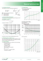
General technical data 4.4. DISSIPATION FACTOR TAN␦ The dissipation or loss factor is defined by its tangent Tan␦ 4.9. CHARACTERISTICS Versus temperature (typical values). 4.9.1. Capacitance drift Versus temperature 4.5. EQUIVALENT SERIES RESISTANCE ESR The relation between ESR and dissipation factor Tan␦ is given in § 4.4. 4.6. IMPEDANCE Z - INDUCTANCE L The impedance is given by: Z =g R2 + (L –1 )2 C 4.9.2. ESR and Z drifts at 100 Hz Versus temperature 4.9.3 Leakage current drift Z and ESR as function of frequency typically follows the chart: Versus temperature 4.7. PERMISSIBLE RIPPLE CURRENT...
Open the catalog to page 2
ELECTROLYTIC ALUMINUM CAPACITORS General technical data 5. SPECIFICATION TO APPLY Electrolytic aluminum capacitors are defined in: 6.3. FAILURE CRITERIA FOR ELECTROLYTIC CAPACITORS. Failure criteria are defined in CECC 30 301 • NF and UTE French national standard • CECC European specifications • IEC international specifications • Non measurable defaults leading to complete failure. • Measurable defaults leading to adjustment losses of the load circuit (failure due to variations). 6.3.1. Non measurable defaults. They might be summed up as: Quality insurance procedures are described in these specifications....
Open the catalog to page 3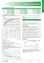
General technical data r.m.s. value according to current waveform. Function Mean value Mean value Mean value 6.4.3. Dissipated power versus case dimension For calculations of ripple currents, considering an internal temperature rise of 10°C Forced or not cooling air can lead to a significant decrease of these values. Consequently, r.m.s. ripple current can be increased as a function of air cooling speed: Ø mm (inches) 66 - 90 36 - 51 This parameter shall be applied to one capacitor alone. For capacitors in bank, ambient temperature must be strictly equal around all capacitors. 6.4.5. Quality guaranty...
Open the catalog to page 4
ELECTROLYTIC ALUMINUM CAPACITORS General technical data Mean time between failures MTBF = 1/FR mesured in years Range FELSIC 85 >350 V FELSIC HC > 350 V SNAPSIC - SNAPSIC HC > 350 V SNAPSIC 4P > 350 V PROMISIC 031 Ø = 6,5 SICAL CO 42 - SICAL > 350 V FELSIC 037 - 039 FELSIC 85 ≤ 350 V FELSIC HC ≤ 350 V CUBISIC CI FRS SNAPSIC 105 - SNAPSIC 105 4P SNAPSIC 105 LP - SNAPSIC HV SNAPSIC - SNAPSIC 4P ≤ 350 V SNAPSIC HC ≤ 350 V ALSIC IR - ALSIC 145 - ALSIC HV VACSIC 150 - VACSIC SICAL CO 42 - SICAL ≤ 350 V PRORELSIC 125 Ø = 6,5 RELSIC 033 PROMISIC 031 Ø > 6,5 FELSIC 125 FRS - SNAPSIC 125 FELSIC HV - FELSIC...
Open the catalog to page 5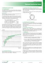
General technical data 8. INFORMATION ON APPLICATION 8.4. MOUNTING SCREW TERMINALS CAPACITORS (FELSIC) Capacitors may be used vertically (terminals on top) or horizontally. When used horizontally, the following position in relation to the safety vent, is recommended: 8.1. CLEANING SOLVENTS Use aliphatic alcohols, such as denatured ethyl alcohol, isopropanol, or butylacetate, or else alkaline d Iluted solutions. Avoid incompatible solvents (halogenous for example). Mounting capacitors in series may be used for operating voltage exceeding UR. See FELSIC in bank. Prominent negative polarity indicator...
Open the catalog to page 6All EXXELIA catalogs and technical brochures
 PHM 912
5 Pages
 DSCC 10004
2 Pages
 CUBISIC SLP
3 Pages
 560P Series
2 Pages
 253P Series
2 Pages
 Tantalum Capacitors Product Catalog
140 Pages
 Ceramic Capacitors Catalog
148 Pages
 Broadband Series
8 Pages
 CF/CFS Series
8 Pages
 FILM& MICA Capacitors Catalog
132 Pages
 Filters and EMC Protections
84 Pages
 EMI-RFI Filters Catalog
82 Pages
 Wound Magnetics Technologies Catalog
123 Pages
 Microwave Components Catalog
204 Pages
 Product & Solutions Catalog
16 Pages
 Electrolytic Aluminium Catalog
124 Pages


- Transformer
- Angular encoder
- Dry transformer
- Electrical rotary joint
- Absolute rotary encoder
- Position transducer
- Encapsulated transformer
- Optical rotary encoder
- Power transformer
- Electronic filter
- Linear position transmitter
- Industrial transformer
- Three-phase transformer
- Electric electrical rotary joint
- Passive electronic filter
- AC electronic filter
- Ceramic capacitor
- Compact electrical rotary joint
- Low-pass electronic filter