Ceramic Capacitors Catalog
1 /148Pages

Ceramic Capacitors Catalog
1 /148Pages
Catalog excerpts

Ceramic Capacitors Standard & Custom Parts
Open the catalog to page 1
Ceramic Capacitors A Worldwide presence Specifications are subject to change without notice. All statements, information and data given herein are presented without guarantee, warranty or responsib Ility of any kind, expressed or implied.
Open the catalog to page 3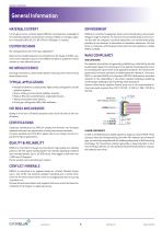
CERAMIC CAPACITORS General Information Taping : dimensions MATERIALS EXPERT For 50 years and as a market leader, EXXELIA’s comprehensive knowledge of the materials properties and performances have enabled us to design capacitors in Porcelain, NPO, BX, 2C1, BP, X7R and -2200ppm/° C ceramics. EXXELIA is committed to applying a robust environmental policy, from product design through to shipment. To control its environmental footprint and reconcile this with the company’ functional imperatives, our environmental policy provides for the reduction or elimination of hazardous substances. We also focus...
Open the catalog to page 4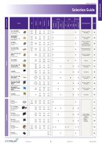
CERAMIC CAPACITORS Selection Guide GENERAL INFORMATION HIGH VOLTAGE STANDARD Main Characteristic OP SERIES Open Mode Chips Capacitors CER /CNR SERIES Low Inductance Chips Capacitors 30 S4 SERIES Safety Capacitors TCE / TCX / TCN / TXR MOLDED SERIES Radial Molded Capacitors NON MAGNETIC CONFORMAL COATED SERIES Radial Dipped Capacitors if CK SERIES Radial Molded Capacitors Power supply, voltage multiplier, radars. • aerospace • space • defence • railways
Open the catalog to page 5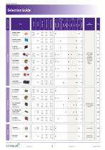
CERAMIC CAPACITORS Selection Guide FEED-THRU HIGH TEMPERATURE HIGH CAPACITANCE Main Characteristic Main Applications R SERIES (CHIPS) High Capacitance Chips Capacitors SV / SC SERIES High Capacitance Stacked Capacitors CNC3X SERIES High Capacitance Stacked Capacitors CEC5X SERIES High Capacitance Stacked Capacitors TEP / TEV SERIES High Capacitance Stacked Capacitors TCN8X SERIES High Capacitance Molded Stacked Capacitors Switch Mode Power Supply, filtering, smoothing, decoupling. • aerospace • space • defence
Open the catalog to page 6
CERAMIC CAPACITORS Selection Guide GENERAL INFORMATION Page Cellular base station equipment Broadband Point to point/ multi-point radios RF generators CP SERIES High Power RF power amplifier Plasma chamber MRI coils CL SERIES High Power RF power amplifier Plasma chamber MRI coils ADDITIONAL AVAILABLE RANGES (consult our website) TCE1X Series Precision, stability, decoupling Power supply, voltage multiplier, radars. Switch Mode Power Supply, filtering, smoothing, decoupling. • aerospace • space • defence Oil drilling, motor control, braking systems. Power amplifier
Open the catalog to page 7
CERAMIC CAPACITORS MLCC STRUCTURE DIELECTRIC CHARACTERISTICS Tin Tin / Lead Gold ' (Solderable layer) Electrodes Margins -Silver or Silver / Palladium (electrodes contact layer) -Polymer (crack protection layer) -Nickel or Copper barrier (leaching protection layer) Insulation Resistance (IR) is the resistance measured under DC voltage across the terminals of the capacitor and consists principally of the parallel resistance shown in the equivalent circuit. As capacitance values and hence the area of dielectric increases, the IR decreases and hence the product (C x IR) is often specified in Q.F...
Open the catalog to page 8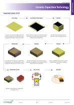
Ceramic Capacitors Technology General characteristics MANUFACTURING STEPS SLIP CASTING ELECTRODE SCREEN PRINTING A slurry, a mix of ceramic powder, binder and solvents, is poured onto conveyor belt inside a drying oven, resulting in a dry ceramic sheet. The electrode ink, made from a metal powder mixed with solvents, is printed onto the ceramic sheets using a screen printing process. The sheets with electrode printed are stacked to create a multilayer structure. Each terminal of the capacitor is dipped in the termination ink, mix of metal powder, solvents and glass frit and the parts are fired...
Open the catalog to page 9
CERAMIC CAPACITORS Ag/Pd/Pt + dipped Sn/Pb 60/40 Nickel (Ni) or Copper (Cu) barriers amplify thermal shock and are not recommended for chip sizes larger than 3030. * Storage must be in a dry environment at a temperature of 20° C with a relative humidity below 50%, or preferably in a package enclosing a desiccant. ** Maintenance only. *** Non magnetic chips series only. SMD ENVIRONMENTAL TESTS Ceramic chip capacitors for SMD are designed to meet test requirements of CECC 32100 and NF C 93133 standards as specified below in compliance with NF C 20700 and IEC 68 standards: STORAGE OF CHIP CAPACITORS...
Open the catalog to page 10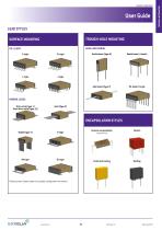
General characteristics User Guide LEAD STYLES SURFACE MOUNTING TROUGH-HOLE MOUNTING AXIAL AND RADIAL PL style Radial leads (Type 6) Radial leads (4 leads) Axial leads (Type 7) RIBBON LEADS Micro-strip (type 1) Short Micro-strip (type 1S) ENCAPSULATION STYLES Radial (Type 3) Ceramic encapsulation Conformal coating Please contact Exxelia sales for any lead configuration not shown. GENERAL INFORMATION CERAMIC CAPACITORS
Open the catalog to page 11
CERAMIC CAPACITORS Large chips above size 2225 are not recommended to be mounted on epoxy board due to thermal expansion coefficient mismatch between ceramic capacitor and epoxy. Where larger sizes are required, it is recommended to use components with ribbon or other adapted leads so as to absorb thermo-mechanical strains. RECOMMENDED FOOTPRINT FOR SMD CAPACITORS Ceramic is by nature a material which is sensitive both thermally and mechanically. Stresses caused by the physical and thermal properties of the capacitors, substrates and solders are attenuated by the leads. Wave soldering is unsuitable...
Open the catalog to page 12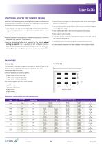
SOLDERING ADVICES FOR IRON SOLDERING Attachment with a soldering iron is discouraged due to ceramic brittleness and the process control limitations. In the event that a soldering iron must be used, the following precautions should be observed: • Use a substrate with chip footprints big enough to allow putting side by side one end of the capacitor and the iron tip without any contact between this tip and the component, • place the capacitor on this footprint, • heat the substrate until the capacitor’s temperature reaches 150° C minimum (preheating step, maximum 1°C per second), • place the hot...
Open the catalog to page 13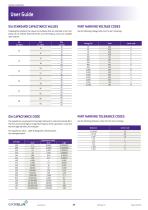
CERAMIC CAPACITORS Following EIA standard, the values and multiples that are indicated in the chart Use the following voltage code chart for part markings: below can be ordered. E48, E96 series and intermediary values are available upon request.
Open the catalog to page 14All EXXELIA catalogs and technical brochures
 PHM 912
5 Pages
 FELSIC HC
17 Pages
 DSCC 10004
2 Pages
 CUBISIC SLP
3 Pages
 560P Series
2 Pages
 253P Series
2 Pages
 Tantalum Capacitors Product Catalog
140 Pages
 Broadband Series
8 Pages
 CF/CFS Series
8 Pages
 FILM& MICA Capacitors Catalog
132 Pages
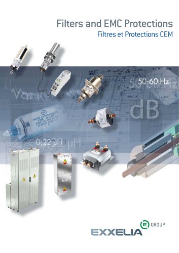 Filters and EMC Protections
84 Pages
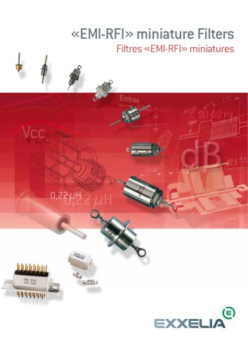 EMI-RFI Filters Catalog
82 Pages
 Wound Magnetics Technologies Catalog
123 Pages
 Microwave Components Catalog
204 Pages
 Product & Solutions Catalog
16 Pages
 Electrolytic Aluminium Catalog
124 Pages


- Transformer
- Angular encoder
- Dry transformer
- Electrical rotary joint
- Absolute rotary encoder
- Position transducer
- Encapsulated transformer
- Optical rotary encoder
- Power transformer
- Electronic filter
- Linear position transmitter
- Industrial transformer
- Three-phase transformer
- Electric electrical rotary joint
- Passive electronic filter
- AC electronic filter
- Compact electrical rotary joint
- Low-pass electronic filter