


- Products
- Catalogs
- News & Trends
- Exhibitions
560P Series

1 / 2 PagesView full catalog
560P Series
Product catalog summary
General Characteristics
The document describes the 560P Series of Wrap-and-Fill High Temperature Polymer Film Capacitors. These capacitors are designed for high-temperature applications and are characterized by their solid tinned wire leads, which must be within ±0.062 inches at the center line at egress, but not less than 0.031 inches from the edge.
The document describes the 560P Series of Wrap-and-Fill High Temperature Polymer Film Capacitors. These capacitors are designed for high-temperature applications and are characterized by their solid tinned wire leads, which must be within ±0.062 inches at the center line at egress, but not less than 0.031 inches from the edge.
Dielectric Characteristics and Configuration
The capacitors are available in various configurations with different dielectric characteristics. The outline dimensions are provided in inches, and the lead wire sizes vary according to the case diameter, ranging from AWG No. 24 for diameters less than 0.200 inches to AWG No. 18 for diameters greater than 0.500 inches.
The capacitors are available in various configurations with different dielectric characteristics. The outline dimensions are provided in inches, and the lead wire sizes vary according to the case diameter, ranging from AWG No. 24 for diameters less than 0.200 inches to AWG No. 18 for diameters greater than 0.500 inches.
Capacitance and Part Numbers
The document lists capacitance values ranging from 0.1 µF to 10 µF, with corresponding part numbers and dimensions for different voltage ratings (320 VDC, 400 VDC, 560 VDC, and 800 VDC). Each capacitance value is associated with specific maximum diameter and length dimensions.
The document lists capacitance values ranging from 0.1 µF to 10 µF, with corresponding part numbers and dimensions for different voltage ratings (320 VDC, 400 VDC, 560 VDC, and 800 VDC). Each capacitance value is associated with specific maximum diameter and length dimensions.
Performance Graphs
Several graphs illustrate the performance characteristics of the capacitors:
Several graphs illustrate the performance characteristics of the capacitors:
- Change in Capacitance vs Temperature: Shows the percentage change in capacitance over a temperature range from -55°C to 150°C.
- Dissipation Factor vs Temperature: Displays the dissipation factor percentage across the same temperature range.
- Change in Insulation Resistance vs Temperature: Indicates the insulation resistance in MΩ-µF from 25°C to 150°C.
- CDF Vrms Max, 125°C Ambient: Provides the maximum Vrms at 125°C ambient across different frequencies.
Additional Information
The document notes that input tolerance numbers are used to complete part numbers, with options for ±10% and ±5% tolerances. Custom configurations and extended/intermediary values are available upon request.
The document notes that input tolerance numbers are used to complete part numbers, with options for ±10% and ±5% tolerances. Custom configurations and extended/intermediary values are available upon request.
See more
Catalog excerpts
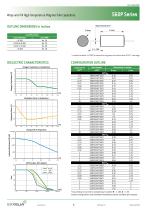
FILM CAPACITORS General characteristics 560P Series Wrap-and-Fill High Temperature Polymer Film capacitors OUTLINE DIMENSIONS in inches Solid tinned wire* L max. D max. Lead Wire Sizes Case Diameter Lead AWG < 0.200 No. 24 0.200 to 0.400 No. 22 0.401 to 0.500 No. 20 > 0.500 No. 18 x 1.750 * Leads to be within ±0.062”at center line at egress, but not less than 0.031” from edge DIELECTRIC CHARACTERISTICS CONFIGURATION OUTLINE Change in Capacitance vs Temperature Insulation Resistance (MΩ-µF) Dissipation Factor vs Temperature Dissipation Factor (%)
Open the catalog to page 2All EXXELIA catalogs and technical brochures
 PHM 912
5 Pages
 FELSIC HC
17 Pages
 DSCC 10004
2 Pages
 CUBISIC SLP
3 Pages
 253P Series
2 Pages
 Tantalum Capacitors Product Catalog
140 Pages
 Ceramic Capacitors Catalog
148 Pages
 Broadband Series
8 Pages
 CF/CFS Series
8 Pages
 FILM& MICA Capacitors Catalog
132 Pages
 Filters and EMC Protections
84 Pages
 EMI-RFI Filters Catalog
82 Pages
 Wound Magnetics Technologies Catalog
123 Pages
 Microwave Components Catalog
204 Pages
 Product & Solutions Catalog
16 Pages
 Electrolytic Aluminium Catalog
124 Pages


Related Searches
- Transformer
- Angular encoder
- Dry transformer
- Electrical rotary joint
- Absolute rotary encoder
- Position transducer
- Encapsulated transformer
- Power transformer
- Optical rotary encoder
- Electronic filter
- Linear position transmitter
- Industrial transformer
- Three-phase transformer
- Passive electronic filter
- Electric electrical rotary joint
- AC electronic filter
- Ceramic capacitor
- Compact electrical rotary joint
- Low-pass electronic filter
*Prices are pre-tax. They exclude delivery charges and customs duties and do not include additional charges for installation or activation options. Prices are indicative only and may vary by country, with changes to the cost of raw materials and exchange rates.
About DirectIndustry
DirectIndustry is a marketplace that offers B2B players a complete experience, from product sourcing to purchase. DirectIndustry is an entity of VirtualExpo Group.
Are you a buyer?
Are you a supplier?